¶ Antennas
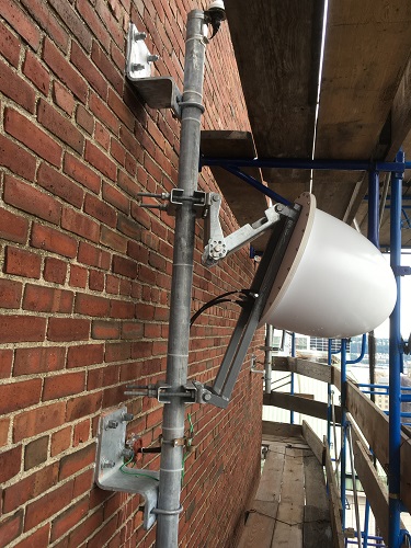
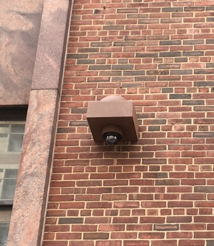
There are two styles of antennas in use in COSMOS. The first style is directional and used exclusively as part of the large node sectors. The second style is omni-directional and used as part of the medium nodes.
 |
 |
|---|---|
| Large node sector antenna (directional) | Medium node antenna (omni-directional) |
¶ Directional (large node sector)
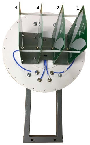
The directional antennas are comprised of a horizontal array of four [attachment:RFSpace_TSA900_directional.pdf ultra-wideband antenna elements]. Each element is oriented in the vertical plane and spaced 3 inches (7.63mm) from its neighbor. The frequency range covered by the antennas is 900 MHz - 12 GHz. However, due to limitations in the power amplifiers, USRPs, and other RF front end components, the actual frequency ranges are 2.4 - 6 GHz for transmit (non-contiguous, see RF front end for details) and 900 MHz - 6 GHz for receive.
A GPS antenna is located near the transmit/receive antenna and provides the GPS signal to the USRPs in the node.
 |
 |
|---|---|
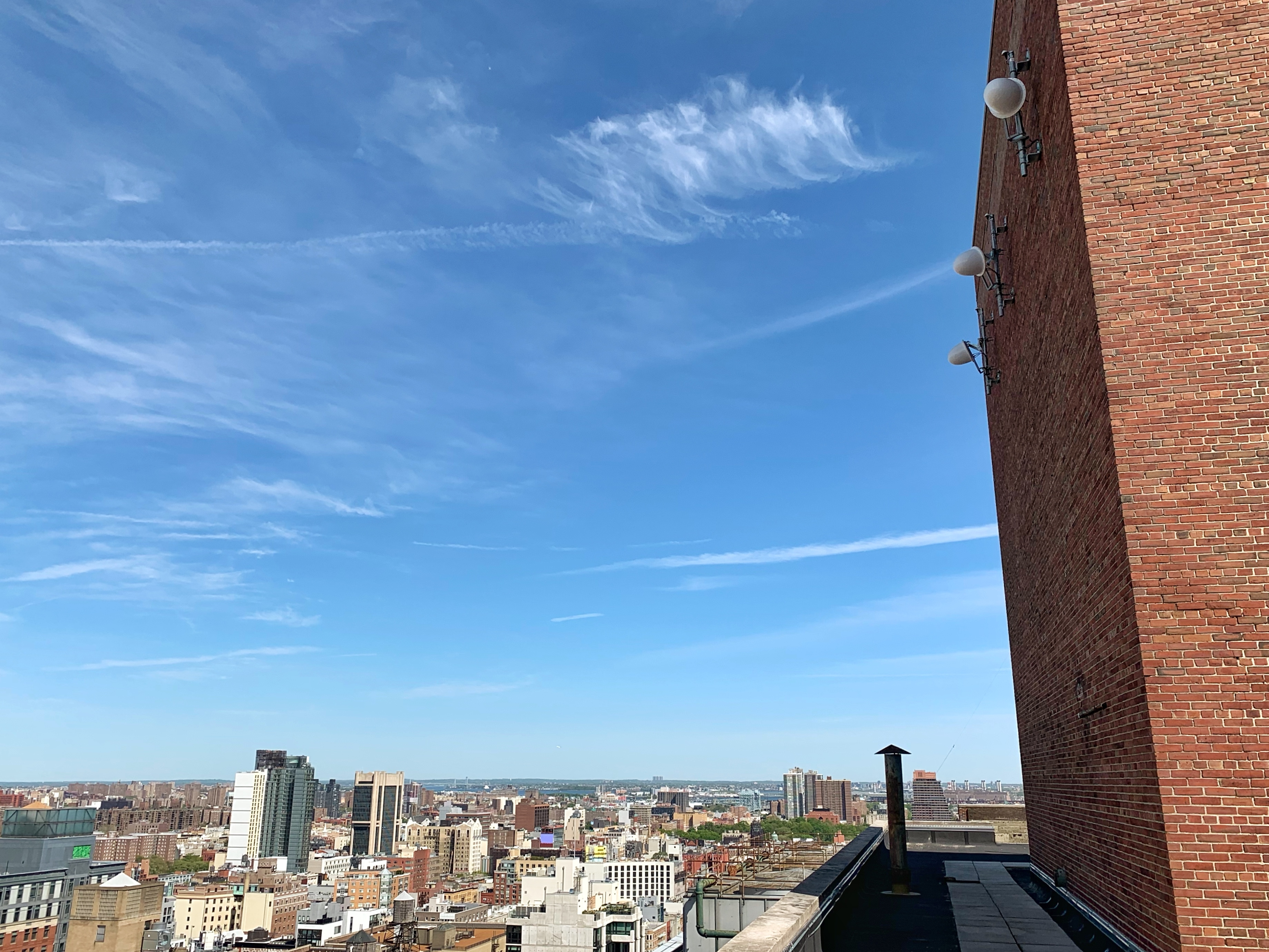
| Directional antenna interior with element numbering | s1-lg1 and s2-lg1's directional antennas from Mudd rooftop |
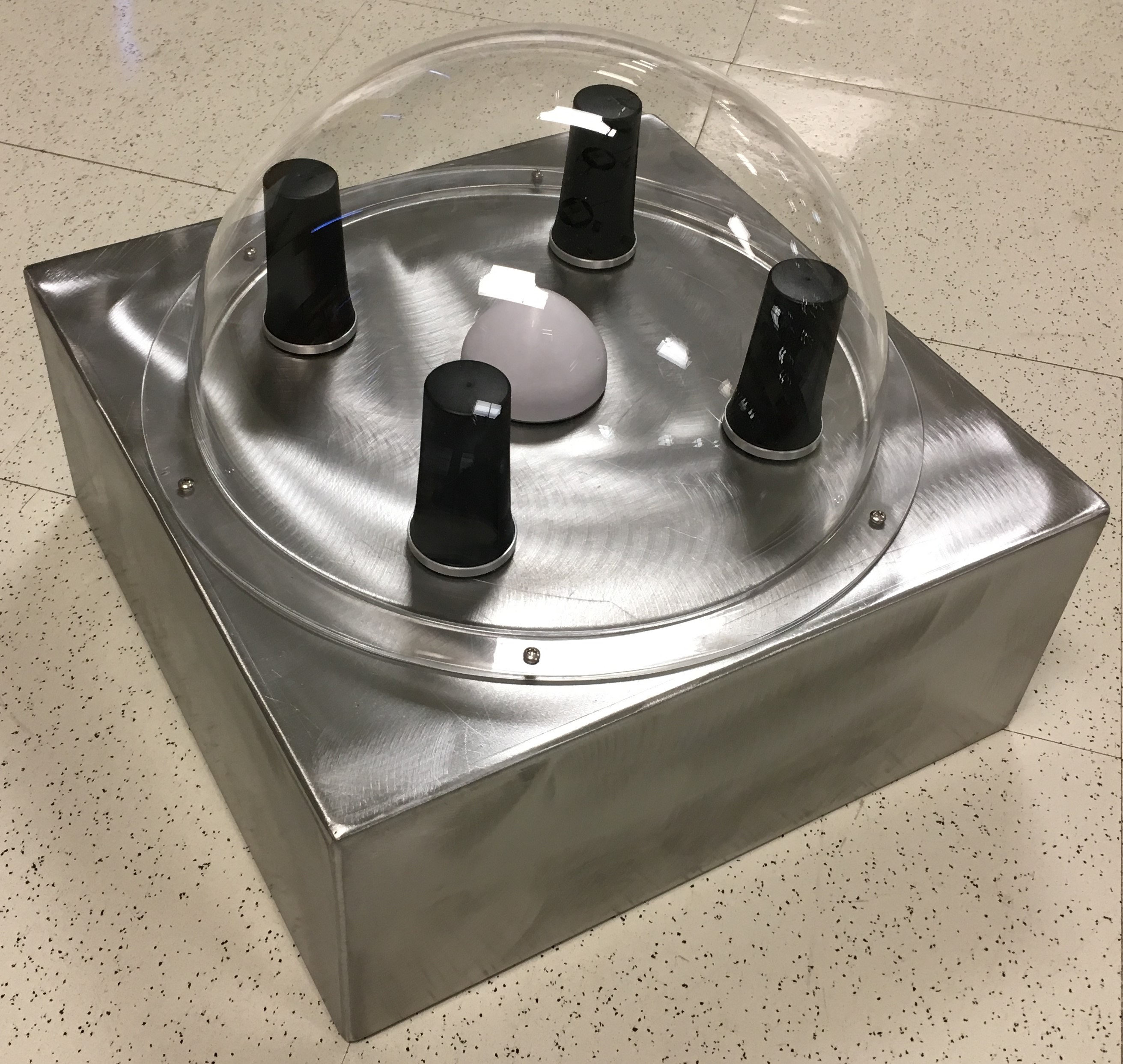
¶ Omni-directional (medium node) without mmWave devices
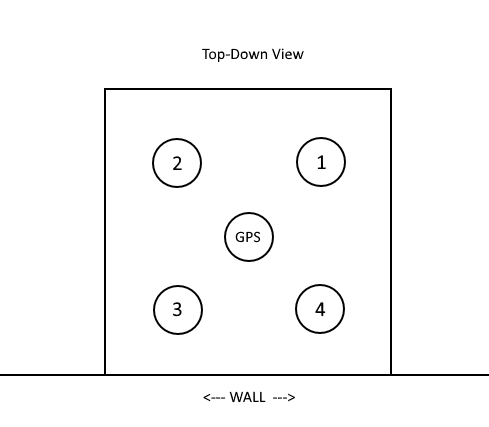
The omni-directional antennas are comprised of four vertically oriented [attachment:MobileMark_RM-WHF_omni.pdf multi-band antennas] in a 6” (15.24 cm) 2x2 square pattern with a 14.25”x14.25” (36.2x36.2 cm) ground plane. The frequency range covered by the antennas is 1.7 - 6 GHz. However, due to limitations in the power amplifiers, USRPs, and other RF front end components, the actual frequency ranges are 2.4 - 6 GHz for transmit (non-contiguous, see RF front end for details) and 1.7 - 6GHz for receive.
A GPS antenna is located in the middle and provides the GPS signal to the USRPs in the node.
||  ||
||  ||
|| 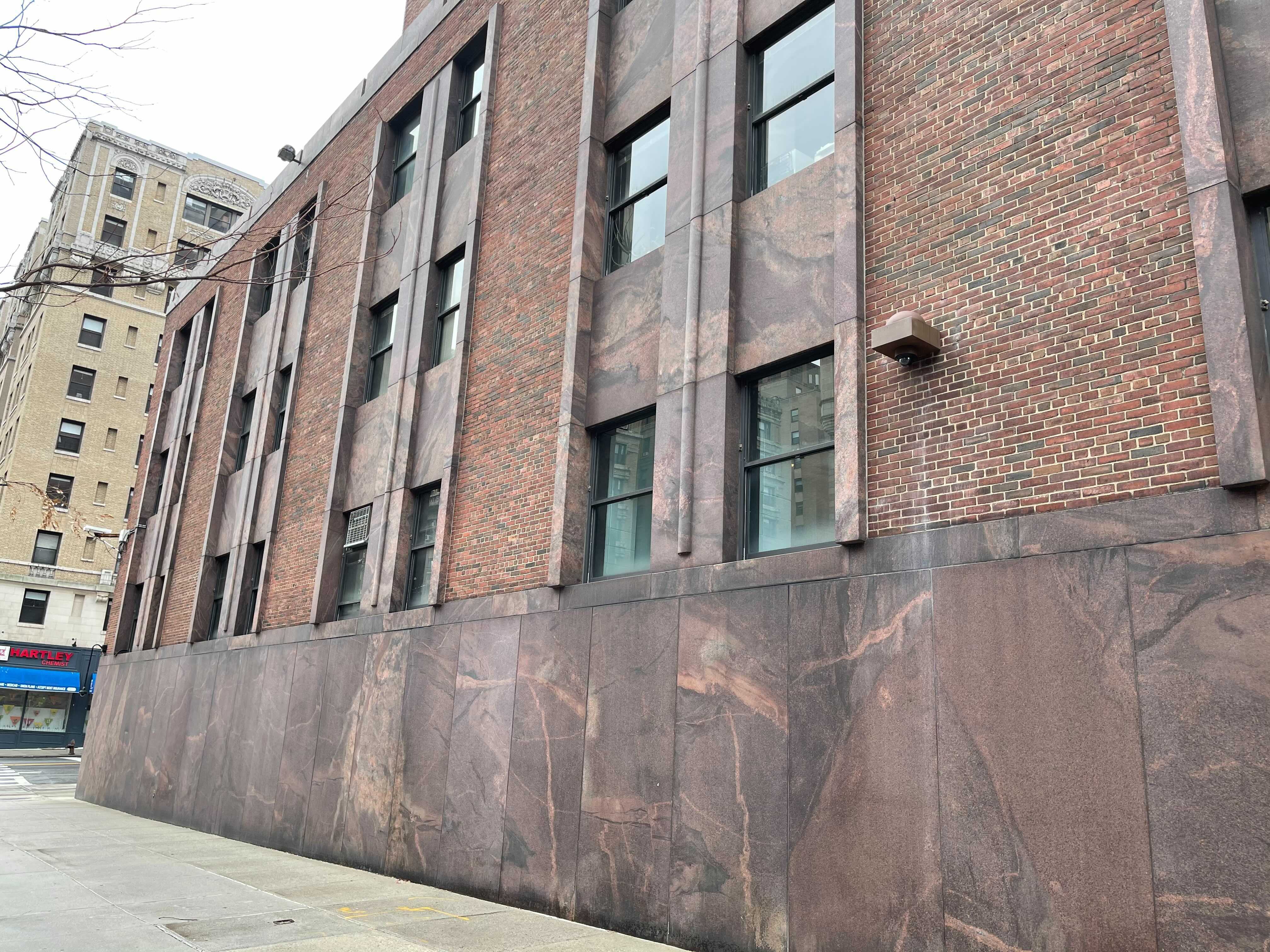
| Unpainted omni-directional antenna | Antenna element numbering | md1's omni-directional antenna from street level |
|---|
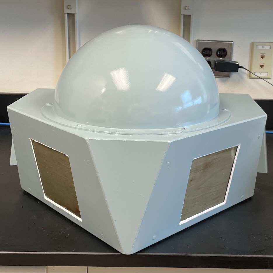
¶ Omni-directional (medium node) with dual mmWave devices
The mmWave version of the medium node antenna housing has the same configuration for the sub-6GHz and GPS antennas as the medium node configuration above. The main difference is in the addition of:
- Dual IBM 28GHz Array
- Fans for cooling the mmWave arrays
- Dual cameras
 |
 |
|---|---|
| mmWave & omni-directional sub-6GHz antenna | Deployed antenna at CCNY |
The mmWave arrays are installed at 45 degrees and down-tilted 12 degrees to give optimal street level coverage. The "window" for each mmWave array is a 5" x 5" opening covered with a 1/8" scratch/impact resistant polycarbonate to protect the array elements.
Design files for the mmWave medium antenna:
- Main Box: [attachment:Medium_Antenna_Dual_PAAM_Drawing_Main_Body.pdf CAD drawing] | [attachment:Medium_Antenna_Dual_PAAM_Main_Box.step STEP file]
- Bottom Plate: [attachment:Medium_Antenna_Dual_PAAM_Drawing_Bottom_Plate.pdf CAD drawing] | [attachment:Medium_Antenna_Dual_PAAM_Bottom_Plate.step STEP file]
Cabling for the medium node antenna consists of:
| =Function = | =Qty= | =Type = |
|---|---|---|
| Sub 6GHz antenna | 4 | N-male to right-angle N-male RG223 coax cable |
| GPS antenna | 1 | N-male to TNC-male right-angle RG223 coax cable |
| PAAM IF | 8 | N-male to N-male right-angle RG223 coax cable |
| PAAM USB debug | 2 | SMA-male to SMA-male RG58 coax cable |
| PAAM ethernet | 2 | Cat 6 UTP ethernet cable w/ right-angle down connector on PAAM side |
| PAAM power | 1 | Cat 6 UTP ethernet cable |
| Cooling fan power & temperature monitoring | 1 | Cat 6 UTP ethernet cable |
| Camera Ethernet | 2 | Cat 6 shielded ethernet cable |