¶ SB4
SB4 is the attenuator-matrix sandbox at WINLAB (Route 1, North Brunswick, NJ) — designed for repeatable, tightly-controlled RF topologies. Ten nodes (node1-1.sb4 through node1-9.sb4, plus srv1.sb4) plus two LTE basestations are all wired into a programmable RF transceiver matrix instead of radiating over the air.
SB4 is the right pick whenever you need a deterministic, repeatable RF channel (no over-the-air variability, no co-channel interference bleed-in from other experiments).
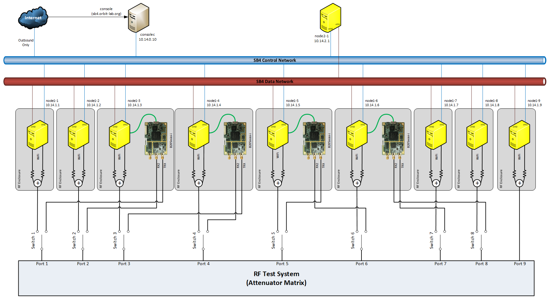
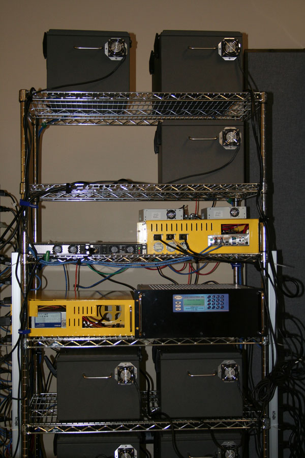 Left: block layout. Right: SB4 in the lab.
¶ What's special about SB4
Each of the 9 main nodes lives inside a Ramsey Electronics RF enclosure (80 dB isolation) and is wired through the enclosure access port to a JFW Industries 50PMA-012 RF transceiver test system. The matrix has 9 input/output ports with programmable attenuators on each pair-wise path: each attenuator can take any value from 0 dB to 63 dB. That gives you 36 simultaneously-controllable pairwise attenuation paths between the SB4 ports.
The topology — pairwise attenuation and the selection between WiFi / SDR on each port — is controlled through the Instrumentation AM service.
¶ Per-node hardware
The nine general-purpose nodes are equipped with a pair of WiFi radios:
- Atheros 5000X mini-PCI (legacy 802.11)
- Intel 6250 mini-PCIe (802.11; the card carries an 802.16 radio too, but the WiMAX basestations have been removed, so it has nothing to associate with)
The Atheros antenna ports are attenuated (-15 dB) and combined (-6 dB power combiner) before reaching the SMA on the enclosure, which feeds into the JFW matrix.
Four nodes (node1-3, node1-4, node1-5, node1-6) also have a USRP B205mini-i SDR whose TX/RX and RX2 ports can be swapped into the matrix in place of the node's WiFi.
¶ Port mapping
The RF matrix has nine input/output ports. By default each port carries that node's WiFi. The Instrumentation AM selDevice command switches selected ports to the SDR instead.
| Port | Default device | Alternative (when selDevice switches in the SDR) |
|---|---|---|
| 1 | node1-1 WiFi | node1-3 SDR TX/RX |
| 2 | node1-2 WiFi | node1-3 SDR RX2 |
| 3 | node1-3 WiFi | node1-4 SDR TX/RX |
| 4 | node1-4 WiFi | node1-4 SDR RX2 |
| 5 | node1-5 WiFi | node1-5 SDR TX/RX |
| 6 | node1-6 WiFi | node1-5 SDR RX2 |
| 7 | node1-7 WiFi | node1-6 SDR TX/RX |
| 8 | node1-8 WiFi | node1-6 SDR RX2 |
| 9 | node1-9 WiFi | — |
Live topology is visible on the scheduler page ("SB4 Topology").
¶ Node-to-node RF path
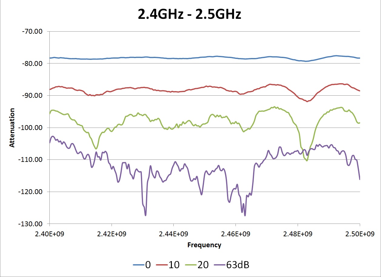
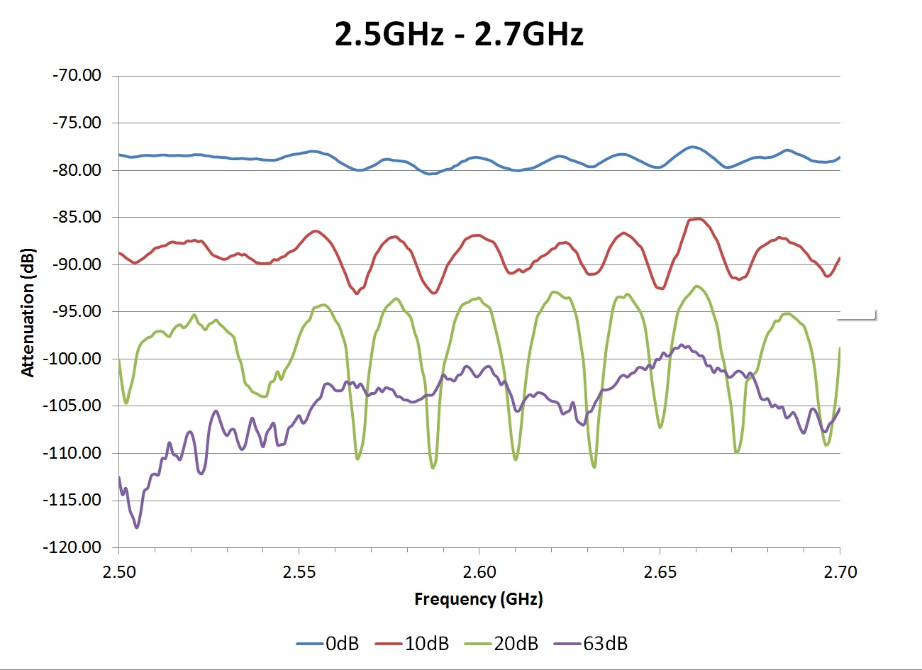
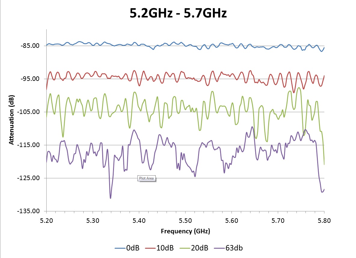
The S12 parameters of the node-to-node path were measured with an Agilent ENA RF Network Analyzer E5070. The analyzer has 110 dB dynamic range, so plots at the largest attenuator settings are limited by instrument noise floor.
 Equivalent node-to-node WiFi RF path through the SB4 matrix.
 |
 |
 |
¶ Per-node hardware (LV-67G class)
The general-purpose SB4 nodes are smaller-form-factor "IRONLAKE CRB" boards with i7-K-class CPUs, 8 GB RAM, and 55 GB SSDs — slightly older than the Q87T-class nodes in SB1 and SB2. srv1.sb4 is a larger server class node.