¶ Getting Started with COSMOS SDR Resources
Transmit and receive a wireless signal between two USRP 2974 software-defined radios on COSMOS sandbox 1 using the built-in UHD example tools.
¶ Overview
This tutorial demonstrates how to run a basic wireless experiment using software-defined radios in the COSMOS testbed. Two COSMOS nodes are used: one to transmit a signal and the other to receive it. The tutorial also covers the basic COSMOS/OMF workflow — loading an image, powering nodes on, and SSHing to them — so it is a good starting point before moving on to more advanced experiments.
The hardware used is the USRP 2974, an all-in-one SDR that contains an onboard System-on-Module (SOM) with an Intel Core i7 processor connected to an X310 FPGA over PCIe. You load the disk image onto the SOM and SSH into it; the FPGA drives the four antenna ports. Communication with the X310 uses the resource=rio0,type=x300 UHD address string rather than an Ethernet interface.
¶ Learning outcomes
After completing this tutorial you will be able to:
- Reserve resources, load a disk image with
omf load, and turn nodes on withomf tell. - Detect the onboard X310 radio with
uhd_find_devicesanduhd_usrp_probe. - Transmit a waveform with
tx_waveforms. - Observe a live spectrum with
rx_ascii_art_dft. - Experiment with different waveform types (SINE, SQUARE) and observe their spectral signatures.
¶ At a glance
| Difficulty | Beginner |
| Estimated time | 45 min |
| Domain / sandbox | sb1.cosmos-lab.org |
| Topic group | Getting started |
| Last verified | Not re-tested (migrated 2026-06-20) |
¶ Prerequisites
Background knowledge
- Basic familiarity with SSH and Linux command line.
- Awareness of the COSMOS experiment workflow — see the COSMOS workflow page.
Account & access
- A COSMOS account — register here.
- An approved reservation on sandbox 1 — see Make a reservation.
- SSH access to the domain console — see SSH access.
¶ Resources required
Devices / nodes
| Resource | Role | Qty | Notes |
|---|---|---|---|
| sdr2-s1-lg1 | Transmitter | 1 | USRP 2974 (onboard X310 via PCIe/RIO0, i7-2600 SOM) |
| sdr2-md1 | Receiver | 1 | USRP 2974 (onboard X310 via PCIe/RIO0) |
Disk images
| Image | Load onto | Provides |
|---|---|---|
| baseline-sdr.ndz | sdr2-s1-lg1, sdr2-md1 | UHD 3.15, GNU Radio 3.8, Ubuntu 18.04; niusrprio PCIe driver loads on boot |
Software components
| Component | Version | Source |
|---|---|---|
| UHD (USRP Hardware Driver) | 3.15 | preinstalled in baseline-sdr.ndz |
| GNU Radio | 3.8 | preinstalled in baseline-sdr.ndz |
| niusrprio (PCIe driver) | as shipped in image | preinstalled; started via niusrprio.service |
Spectrum / RF / special
Over-the-air transmit on sandbox 1. Examples use 2.4 GHz carrier. Stay within your reservation's allowed spectrum and keep gains modest.
¶ Topology
Two USRP 2974 nodes on sandbox 1. Each node is an all-in-one unit: the SOM (i7 host CPU) communicates with the onboard X310 FPGA over an internal PCIe bus (UHD address resource=rio0,type=x300). The nodes transmit and receive over the air via their antenna ports. Both are controlled from the sandbox console at console.sb1.cosmos-lab.org.
¶ Setup
-
Reserve resources on sandbox 1 and log into the console:
ssh YOUR_USERNAME@console.sb1.cosmos-lab.org -
Make sure the resources are off before imaging:
omf tell -a offh -t system:topo:allres -
Load the baseline SDR image onto both nodes:
omf load -i baseline-sdr.ndz -t sdr2-s1-lg1,sdr2-md1Below is an annotated example of the
omf loadoutput:INFO NodeHandler: Reading domain configuration ... INFO NodeHandler: Add domain http - http://internal1.orbit-lab.org:5054/ INFO NodeHandler: Slice ID: default_slice INFO NodeHandler: Experiment ID: default_slice-2026-05-10t12.34.56.000-04.00 INFO ALL_UP_AND_INSTALLED: Event triggered. Starting the associated tasks. INFO exp: Loading image baseline-gnu-12-04-32bit.ndz onto node1-1.sb7.cosmos-lab.org INFO frisbeed: Multicast loading at 1.2 GB/s ... [|||||||... ] 47% 312/660 MB INFO frisbeed: Multicast loading at 1.2 GB/s ... [||||||||||||||] 100% 660/660 MB INFO exp: Image loaded — sending node POWEROFF INFO exp: Sending POWERON to node1-1.sb7.cosmos-lab.org INFO stdlib: Waiting for nodes (Up/Down/Total): 0/1/1 - (still down: node1-1.sb3) [10 sec.] INFO stdlib: Waiting for nodes (Up/Down/Total): 0/1/1 - (still down: node1-1.sb3) [30 sec.] INFO stdlib: Waiting for nodes (Up/Down/Total): 1/0/1 — all nodes UP after 67 sec. INFO run: Experiment default_slice-2026-05-10t12.34.56.000-04.00 finished after 1:18The output has two phases:
- Pre-image phase (typically the first ~10 seconds) — OMF talks to the PXE service to set the node's next boot to the imaging environment, then powers the node off and on. During this window you'll see
Waiting for nodesmessages while OMF waits for the imaging environment to come up over PXE. - Imaging phase — once the node has PXE-booted,
frisbeedmulticasts the image to it. Progress is shown as a percentage. When the image is fully written, OMF sends a POWEROFF and then a POWERON to boot the freshly-imaged node from its disk.
Always check the output to make sure all nodes were successfully imaged. If any node fails, it will be noted at the end of the output.
- Pre-image phase (typically the first ~10 seconds) — OMF talks to the PXE service to set the node's next boot to the imaging environment, then powers the node off and on. During this window you'll see
-
Turn the nodes on and confirm they are up:
omf tell -a on -t sdr2-s1-lg1,sdr2-md1 omf stat -t sdr2-s1-lg1,sdr2-md1 -
After waiting for the nodes to fully boot, SSH to each from the console:
ssh root@sdr2-s1-lg1Note: Server-class nodes can take several minutes to complete the boot process. Wait until the node is fully up before attempting SSH.
-
You can verify the node hardware by running
lshw:H/W path Device Class Description ========================================================== system MahoBay Platform (System SKUNumber) /0 bus Los Lunas 2 /0/4 processor Intel(R) Core(TM) i7-2600 CPU @ 3.40GHz /0/4/6 memory 32KiB L1 cache /0/4/7 memory 256KiB L2 cache /0/4/8 memory 8MiB L3 cache /0/5 memory 32KiB L1 cache /0/0 memory 128KiB BIOS /0/30 memory 8GiB System Memory /0/30/0 memory 4GiB DIMM DDR3 Synchronous 1333 MHz (0.8 ns) /0/30/1 memory DIMM [empty] /0/30/2 memory 4GiB DIMM DDR3 Synchronous 1333 MHz (0.8 ns) /0/30/3 memory DIMM [empty] /0/100 bridge 2nd Generation Core Processor Family DRAM Controller /0/100/1 bridge Xeon E3-1200/2nd Generation Core Processor Family PCI Express Root Port /0/100/1/0 enp1s0 network 82574L Gigabit Network Connection /0/100/2 /dev/fb0 display 2nd Generation Core Processor Family Integrated Graphics Controller /0/100/16 communication 6 Series/C200 Series Chipset Family MEI Controller #1 /0/100/1a bus 6 Series/C200 Series Chipset Family USB Enhanced Host Controller #2 /0/100/1a/1 usb1 bus EHCI Host Controller /0/100/1a/1/1 bus Integrated Rate Matching Hub /0/100/1b card0 multimedia 6 Series/C200 Series Chipset Family High Definition Audio Controller /0/100/1b/0 input10 input HDA Intel PCH Line Out CLFE /0/100/1b/1 input11 input HDA Intel PCH Line Out Side /0/100/1b/2 input12 input HDA Intel PCH Front Headphone /0/100/1b/3 input5 input HDA Intel PCH Rear Mic /0/100/1b/4 input6 input HDA Intel PCH Front Mic /0/100/1b/5 input7 input HDA Intel PCH Line /0/100/1b/6 input8 input HDA Intel PCH Line Out Front /0/100/1b/7 input9 input HDA Intel PCH Line Out Surround /0/100/1c bridge 6 Series/C200 Series Chipset Family PCI Express Root Port 1 /0/100/1c.4 bridge 6 Series/C200 Series Chipset Family PCI Express Root Port 5 /0/100/1c.4/0 enp3s0 network 82574L Gigabit Network Connection /0/100/1c.5 bridge 6 Series/C200 Series Chipset Family PCI Express Root Port 6 /0/100/1c.5/0 enp4s0 network 82574L Gigabit Network Connection /0/100/1c.6 bridge 6 Series/C200 Series Chipset Family PCI Express Root Port 7 /0/100/1c.6/0 network AR928X Wireless Network Adapter (PCI-Express) /0/100/1d bus 6 Series/C200 Series Chipset Family USB Enhanced Host Controller #1 /0/100/1d/1 usb2 bus EHCI Host Controller /0/100/1d/1/1 bus Integrated Rate Matching Hub /0/100/1e bridge 82801 PCI Bridge /0/100/1e/8 network AR5212/5213/2414 Wireless Network Adapter /0/100/1f bridge Q67 Express Chipset LPC Controller /0/100/1f/0 system PnP device PNP0c02 /0/100/1f/1 system PnP device PNP0b00 /0/100/1f/2 generic PnP device INT3f0d /0/100/1f/3 communication PnP device PNP0501 /0/100/1f/4 communication PnP device PNP0501 /0/100/1f/5 communication PnP device PNP0501 /0/100/1f/6 communication PnP device PNP0501 /0/100/1f/7 input PnP device PNP0303 /0/100/1f/8 input PnP device PNP0f13 /0/100/1f/9 system PnP device PNP0c02 /0/100/1f/a system PnP device PNP0c01 /0/100/1f.2 scsi0 storage 6 Series/C200 Series Chipset Family Desktop SATA Controller (IDE mode, ports 0-3) /0/100/1f.2/0.0.0 /dev/sda disk 60GB EDGE Boost Pro S /0/100/1f.2/0.0.0/1 /dev/sda1 volume 20GiB EXT4 volume /0/100/1f.3 bus 6 Series/C200 Series Chipset Family SMBus Controller /0/100/1f.5 storage 6 Series/C200 Series Chipset Family Desktop SATA Controller (IDE mode, ports 4-5) /1 power TBD by ODM /2 input0 input Power Button /3 input4 input Video BusConfirm the node type matches what you reserved. On sb1 you should see a Los Lunas 2 mainboard with an i7-2600 CPU. If the output differs, check whether the node was re-imaged or re-cabled before your reservation.
¶ Instructions
¶ Step 1 — Detect the radio
The USRP 2974 uses a PCIe driver (niusrprio) to control the onboard X310 FPGA. In the provided image, this driver loads automatically on boot. If it does not, restart it manually:
systemctl restart niusrprio.service
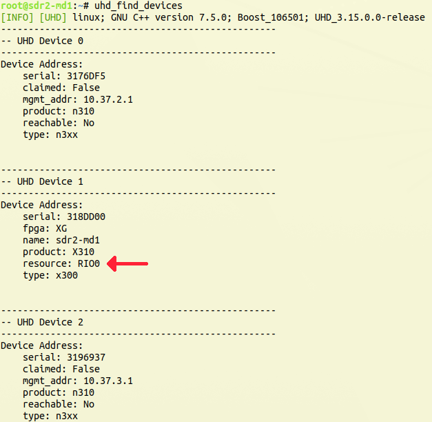
Use uhd_find_devices to confirm the onboard X310 is detected:
uhd_find_devices
Note: Running
uhd_find_deviceswith no arguments may also list other SDR resources reachable over the network. Focus on the onboard X310 (RIO0).
Use uhd_usrp_probe to get detailed information. Specifying resource=rio0 ensures only the directly connected radio is probed:
uhd_usrp_probe --args "resource=rio0,type=x300"
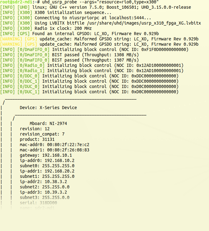
If either command fails, see the Troubleshooting section. Detailed driver installation and firmware update notes are available on the Krypton usage page.
¶ Step 2 — Start the spectrum viewer on the receiver
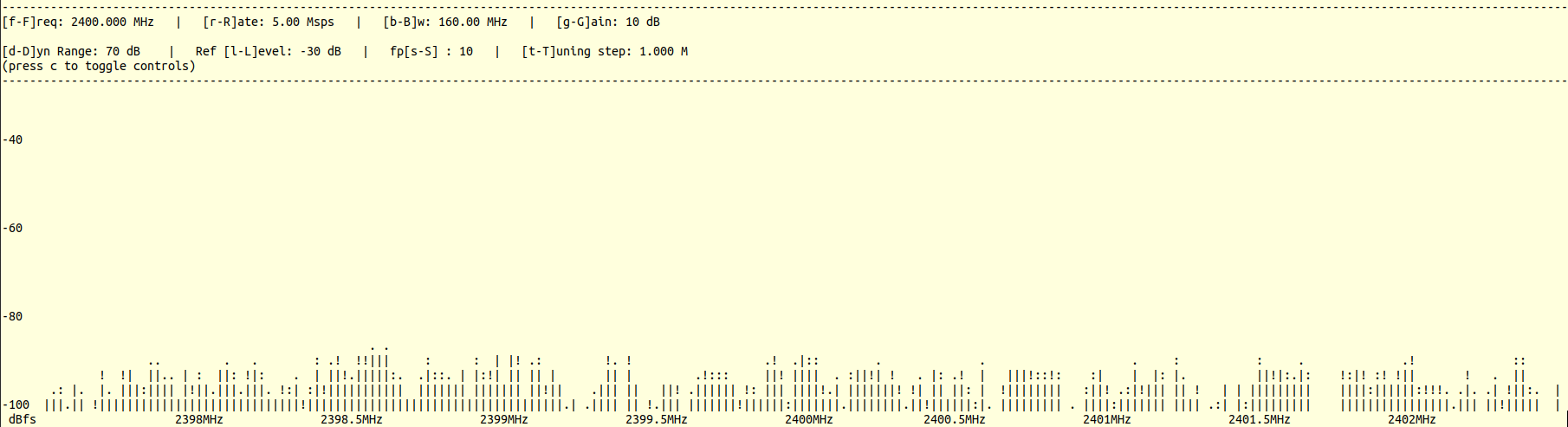
SSH to sdr2-md1 and start rx_ascii_art_dft watching 2.4 GHz:
/usr/lib/uhd/examples/rx_ascii_art_dft --args "resource=rio0,type=x300" --freq 2400e6 --rate 5e6 --frame-rate 10 --gain 10 --ref-lvl -30 --dyn-rng 70
You should see a live DFT display. With no transmitter running, it shows only noise:
¶ Step 3 — Transmit a sine wave
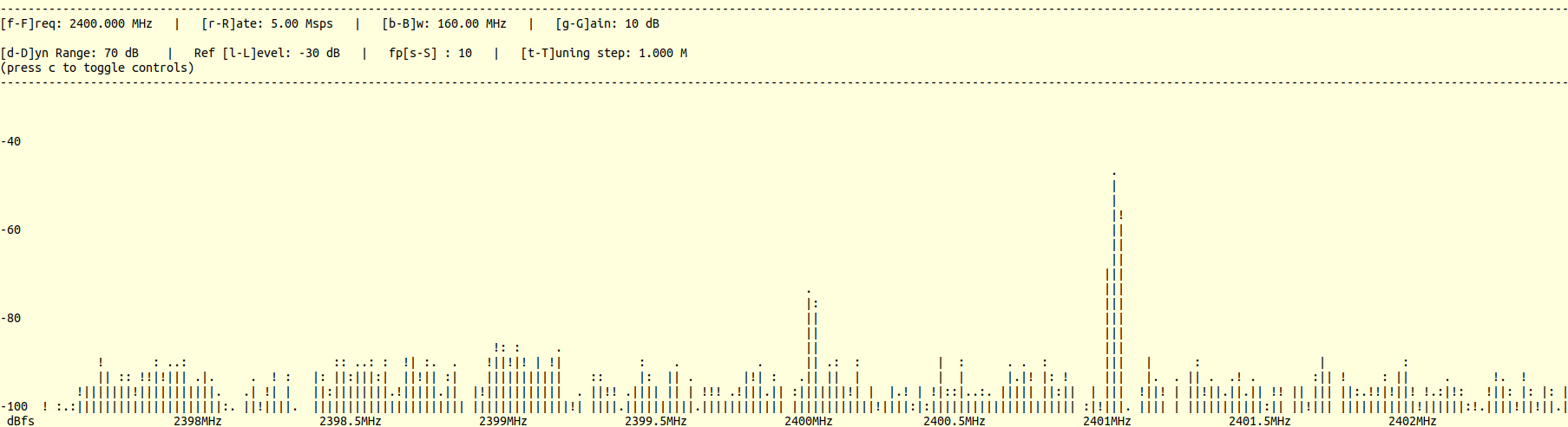
In a separate SSH session, connect to sdr2-s1-lg1 and start tx_waveforms transmitting a 1 MHz sine on a 2.4 GHz carrier:
/usr/lib/uhd/examples/tx_waveforms --args="resource=rio0,type=x300" --wave-freq 1e6 --wave-type SINE --freq 2400e6 --rate 5e6 --gain 10 --ampl 0.2
On the DFT display on sdr2-md1, you should now see a peak representing the transmitted signal:
¶ Step 4 — Transmit a square wave
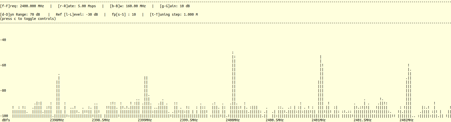
Change the waveform type to SQUARE to observe the spectral characteristics of a square wave (multiple peaks from harmonics):
/usr/lib/uhd/examples/tx_waveforms --args="resource=rio0,type=x300" --wave-freq 1e6 --wave-type SQUARE --freq 2400e6 --rate 5e6 --gain 10 --ampl 0.2
The spectrum on sdr2-md1 should now show multiple peaks at the fundamental frequency and its harmonics:
Both tx_waveforms and rx_ascii_art_dft accept --help to list all available arguments. Additional example applications are in /usr/lib/uhd/examples/.
Source code for all UHD example applications: https://github.com/EttusResearch/uhd/tree/UHD-3.15.LTS/host/examples
¶ Verification
uhd_find_devicesanduhd_usrp_probereturn the onboard X310 radio (RIO0).- With the transmitter running (
tx_waveformsSINE),rx_ascii_art_dfton the receiver shows a clear peak at 2.4 GHz. - Stopping the transmitter causes the peak to collapse to the noise floor.
- Switching to SQUARE wave produces visible harmonic peaks in the spectrum display.
¶ Cleanup
omf tell -a offh -t sdr2-s1-lg1,sdr2-md1
No omf save is needed unless you modified the image and want to preserve changes.
¶ Troubleshooting
| Symptom | Likely cause | Fix |
|---|---|---|
uhd_find_devices returns no devices |
PCIe driver not loaded | Run systemctl restart niusrprio.service and retry |
uhd_usrp_probe fails or times out |
FPGA firmware mismatch | Check the Krypton usage page for firmware update instructions |
| SSH to node fails / connection refused | Node not finished booting | Wait a few more minutes; server-class nodes can take several minutes to fully boot |
omf load shows some nodes failed to image |
Node failed to PXE-boot or write image | Check OMF output for which nodes failed; retry omf load for those nodes |
| Spectrum shows only noise with transmitter running | Wrong frequency or args mismatch | Confirm --freq matches on both tx_waveforms and rx_ascii_art_dft; confirm transmitter is still streaming |
¶ References
- COSMOS sandbox 1 hardware page
- COSMOS workflow page
- USRP 2974 product page
- UHD example source code (UHD-3.15.LTS)
- Make a reservation
- SSH access to the console
Author(s): COSMOS team · Last verified: Not re-tested (migrated 2026-06-20) · Tested image/release: baseline-sdr.ndz (UHD 3.15, GNU Radio 3.8, Ubuntu 18.04) · Tags: sdr, uhd, usrp, getting-started, beginner