¶ Full-Duplex Wireless with FlexICoN RF Cancellers
Explore simultaneous transmit-and-receive on a single antenna using Columbia FlexICoN Gen-1 and Gen-2 RF canceller hardware integrated into the ORBIT and COSMOS testbeds, and observe self-interference cancellation (SIC) in both the RF and digital domains.
¶ Overview
This tutorial covers two complementary experimental setups for full-duplex (FD) wireless:
Part 1 — COSMOS Sandbox 2 (Gen-2 FDE cancellers): Four Columbia FlexICoN Gen-2 Wideband Frequency-Domain Equalization (FDE) RF canceller boxes are integrated in COSMOS Sandbox 2 (sb2), each connected to a transceiver on a USRP X310. Using GNU Radio flowgraphs provided in the flexicon-cosmos-v1.ndz image, users can configure the FDE canceller parameters via GUI sliders and visualize node-level self-interference cancellation.
Part 2 — ORBIT Main Grid (Gen-1 narrowband canceller): A single Columbia FlexICoN Gen-1 narrowband amplitude- and phase-based RF canceller is integrated at node11-10 in the ORBIT main grid, paired with a USRP N210. Users can run UHD-based and GNU Radio-based experiments to observe RF and digital SIC, and optionally bring in a secondary transmitter (node13-8) to demonstrate simultaneous TX/RX of an external signal while cancelling self-interference.
All source code is available at the FlexICoN GitHub repository.
¶ Learning outcomes
After completing this tutorial you will be able to:
- Load and configure a full-duplex SDR node image on COSMOS/ORBIT testbed resources.
- Configure the Gen-2 FDE and Gen-1 narrowband FlexICoN RF canceller boxes using the SUB-20 SPI interface.
- Run GNU Radio flowgraphs that visualize self-interference cancellation in real time.
- Use the UHD-based
fd_transceiver_simpleexperiment to measure RF and digital SIC power levels from the command line. - Optimize canceller parameters iteratively to minimize residual self-interference.
- Save a customized node image to preserve your experimental configuration.
¶ At a glance
| Difficulty | Intermediate |
| Estimated time | 2–3 hours (Part 1); 1–2 hours (Part 2) |
| Domain / sandbox | Part 1: sb2.cosmos-lab.org; Part 2: grid.cosmos-lab.org |
| Topic group | Misc |
| Last verified | Not re-tested (migrated 2026-06-20) |
¶ Prerequisites
Background knowledge
- Basic RF and SDR concepts (carrier frequency, self-interference, I/Q sampling).
- Familiarity with GNU Radio Companion (GRC) and opening/running flowgraphs.
- Familiarity with basic OMF commands (
omf load,omf tell,omf stat,omf save).
Account & access
- A COSMOS account — register here.
- An approved reservation on the relevant domain (sb2 or grid) — see Make a reservation.
- SSH access to the domain console — see SSH access.
- X11 forwarding capable SSH client (required for GNU Radio GUI). On macOS,
-Ymay be needed instead of-X.
¶ Resources required
Devices / nodes
| Resource | Role | Qty | Notes |
|---|---|---|---|
| srv2-lg1 (COSMOS sb2) | Full-duplex experiment server | 1 | COSMOS sandbox server; hosts Gen-2 FDE experiments (Part 1) |
| node11-10 (ORBIT grid) | Full-duplex SDR node | 1 | Equipped with USRP N210 + Gen-1 FlexICoN RF canceller; SUB-20 serial 48AB (Part 2) |
| node13-8 (ORBIT grid) | Optional secondary transmitter | 1 | Used in Part 2 to demonstrate simultaneous TX/RX; TODO: verify node still exists |
Disk images
| Image | Load onto | Provides |
|---|---|---|
| flexicon-cosmos-v1.ndz | srv2-lg1 | GNU Radio 3.8.2, UHD 4.2.1, Gen-2 FDE experiment flowgraphs, SUB-20 support, Eigen 3.3.4 |
| flexicon-orbit-v4.ndz | node11-10 | GNU Radio OOT modules, UHD, Gen-1 canceller experiments, Eigen 3.3.4, flexicon_orbit source |
| baseline-sdr.ndz | node13-8 (optional) | Standard UHD tools including tx_waveforms |
Software components
| Component | Version | Source |
|---|---|---|
| UHD (USRP Hardware Driver) | 4.2.1 (COSMOS); 3.10.x (ORBIT) | preinstalled in respective images |
| GNU Radio | 3.8.2 (COSMOS); TODO: verify version (ORBIT) | preinstalled in respective images |
| gr-fullduplex (OOT module) | as shipped in image | GitHub |
| Eigen C++ Library | 3.3.4 | preinstalled in images |
| SUB-20 USB-to-SPI interface driver | as shipped in image | xdimax.com |
Spectrum / RF / special
- Part 1 (COSMOS sb2): 920 MHz default center frequency; 20 MHz bandwidth. Located in a controlled lab environment at Columbia University. Uses a shielded/indoor environment.
- Part 2 (ORBIT grid): 900–1000 MHz (Gen-1 canceller is narrowband, optimized for ~900 MHz). Indoor testbed.
- Both setups require X11 forwarding for the GNU Radio GUI.
¶ Topology
Part 1 — COSMOS Sandbox 2
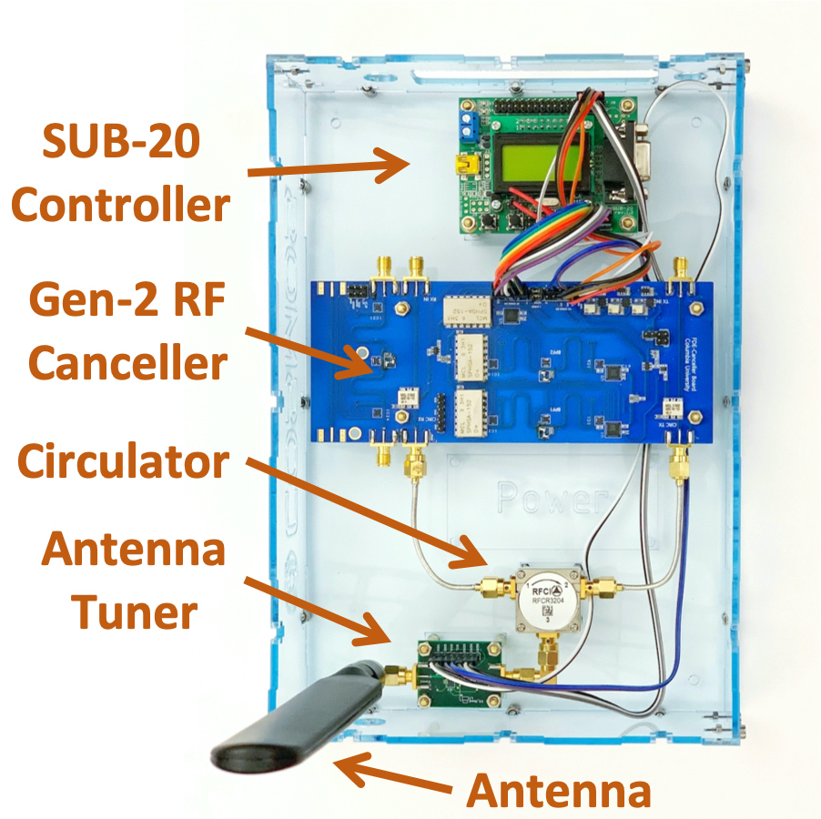
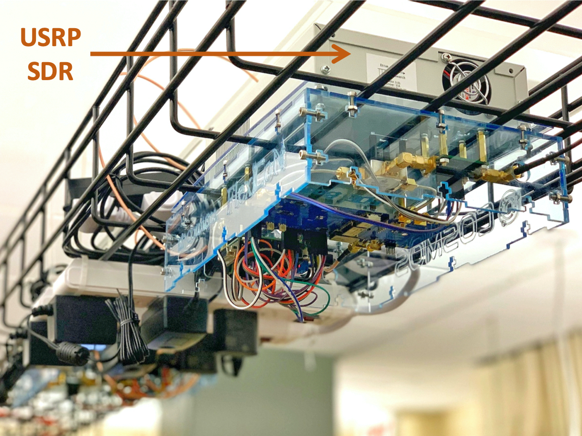
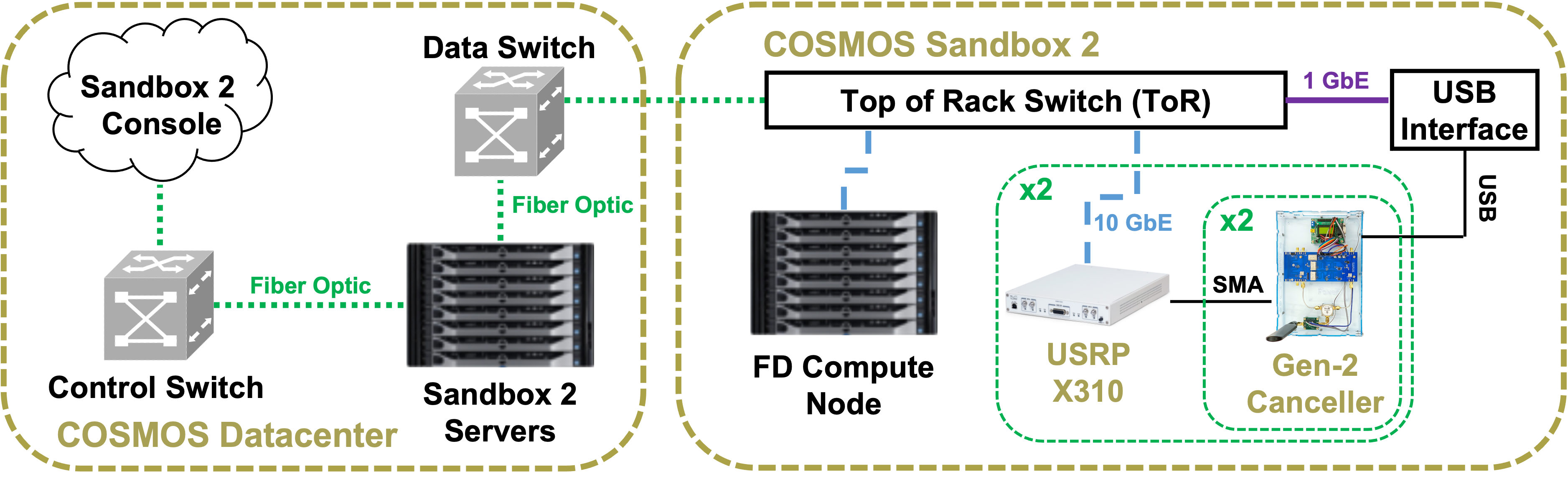
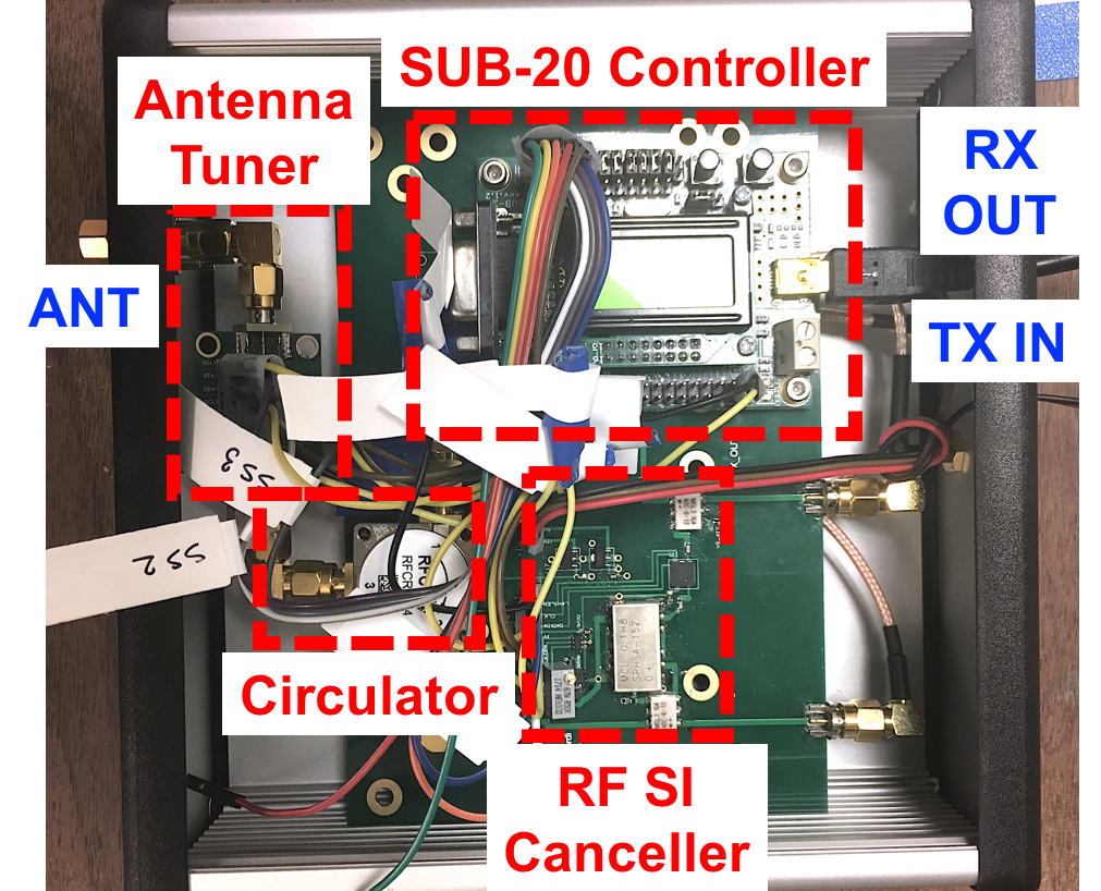
Up to 4 FlexICoN Gen-2 FDE RF Canceller Boxes are rack-mounted in COSMOS Sandbox 2. Each canceller box consists of a circulator, antenna tuner, Gen-2 FDE RF canceller PCB, and a SUB-20 USB-to-SPI adapter. Each box connects to one transceiver of a USRP X310 SDR:
- USRP X310 at
10.113.2.71— transceivers A:0 (Radio 1) and B:0 (Radio 2) - USRP X310 at
10.113.2.72— transceivers A:0 (Radio 3) and B:0 (Radio 4)
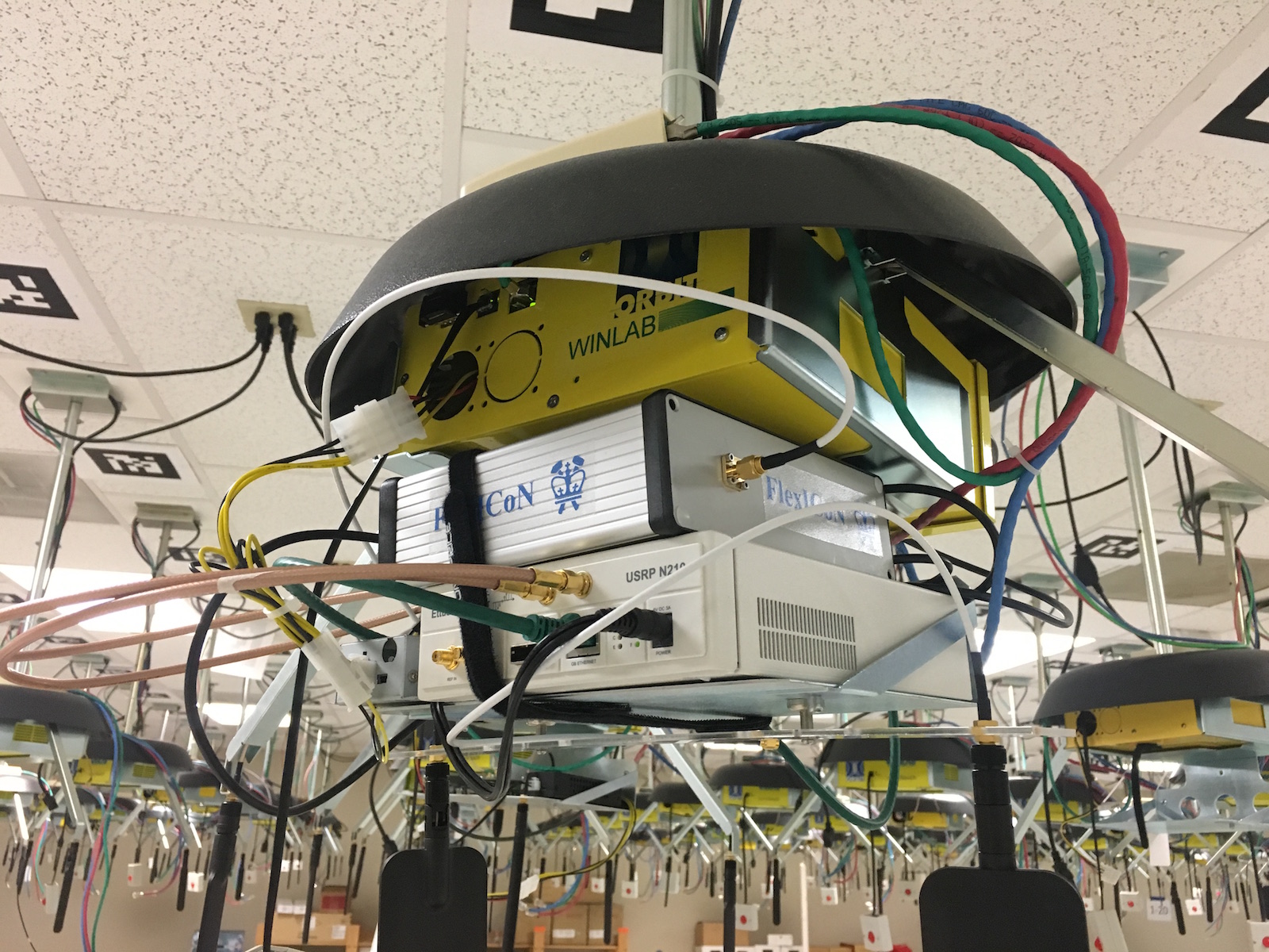
Both X310s connect to the COSMOS servers over 10 Gigabit Ethernet. The experiment server srv2-lg1 controls the USRPs and SUB-20 devices, and runs the GNU Radio flowgraphs.
Part 2 — ORBIT Main Grid
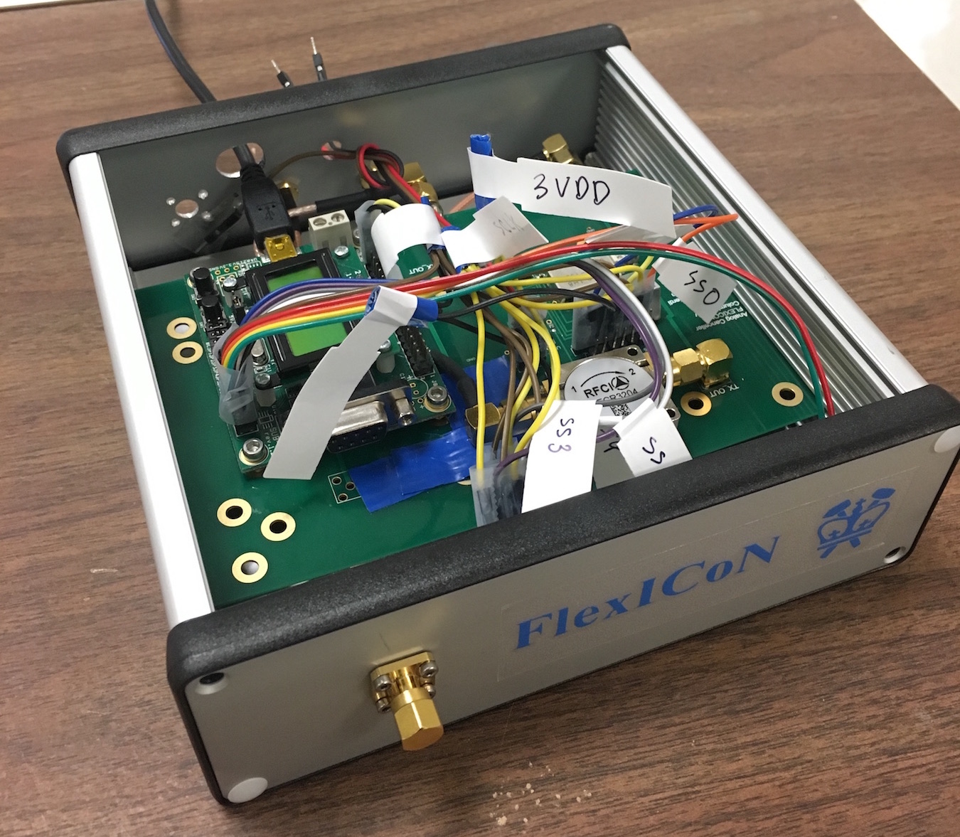
node11-10 in the ORBIT main grid is equipped with a USRP N210 connected over Ethernet (eth2, configured as 192.168.10.1/24; USRP at 192.168.10.2) and a Gen-1 FlexICoN RF Canceller box connected via USB (SUB-20 serial 48AB). All control occurs from the ORBIT grid console.
¶ Setup
¶ Part 1 — COSMOS Sandbox 2
-
Reserve the sandbox and log into the console with X11 forwarding:
ssh -X <username>@console.sb2.cosmos-lab.orgNote: on macOS, use
-Yinstead of-X. -
Ensure the server is powered off before imaging:
omf tell -a offh -t srv2-lg1You should receive a
Reply: OKmessage. If not, see Troubleshooting. -
Load the full-duplex image (this can take 5–10 minutes):
omf load -o 1800 -i flexicon-cosmos-v1.ndz -t srv2-lg1Let the command run to completion. Confirm output similar to:
INFO exp: ----------------------------- INFO exp: Imaging Process Done INFO exp: 1 node successfully imaged - Topology saved .... INFO exp: ----------------------------- -
Power on the server:
omf tell -a on -t srv2-lg1Wait a couple of minutes for the server to fully boot.
-
Log into the server with X11 forwarding:
ssh -X root@srv2-lg1 -
Optimize network interfaces for UHD and GNU Radio:
./optimizeInterfaces
¶ Part 2 — ORBIT Main Grid
-
Reserve the grid domain and log into the console with X11 forwarding:
ssh -X <username>@console.grid.cosmos-lab.org -
Power off the full-duplex node before imaging:
omf tell -a offh -t node11-10 -
Load the full-duplex node image (takes a few minutes):
omf load -i flexicon-orbit-v4.ndz -t node11-10 -
Power on the node:
omf tell -a on -t node11-10 -
Log into the node with X11 forwarding:
ssh -X root@node11-10After login, the
flexicon_orbitfolder should be present under~/. -
Configure the USRP Ethernet interface:
ifconfig eth2 192.168.10.1 netmask 255.255.255.0 up -
Tune kernel socket buffers for UHD:
sudo sysctl -w net.core.rmem_max=50000000 sudo sysctl -w net.core.wmem_max=50000000 -
Verify USRP N210 is reachable (serial should be
F331D4):uhd_find_devices
¶ Instructions
¶ Part 1 — Gen-2 FDE Cancellers (COSMOS sb2)
¶ Step 1 — Configure an FD Radio with wifi_node_level_sic_tune
Open GNU Radio Companion (the GUI will appear via X11 forwarding):
gnuradio-companion &
Open the experiment file:
~/Experiments/Node/wifi_node_level_sic_tune.grc
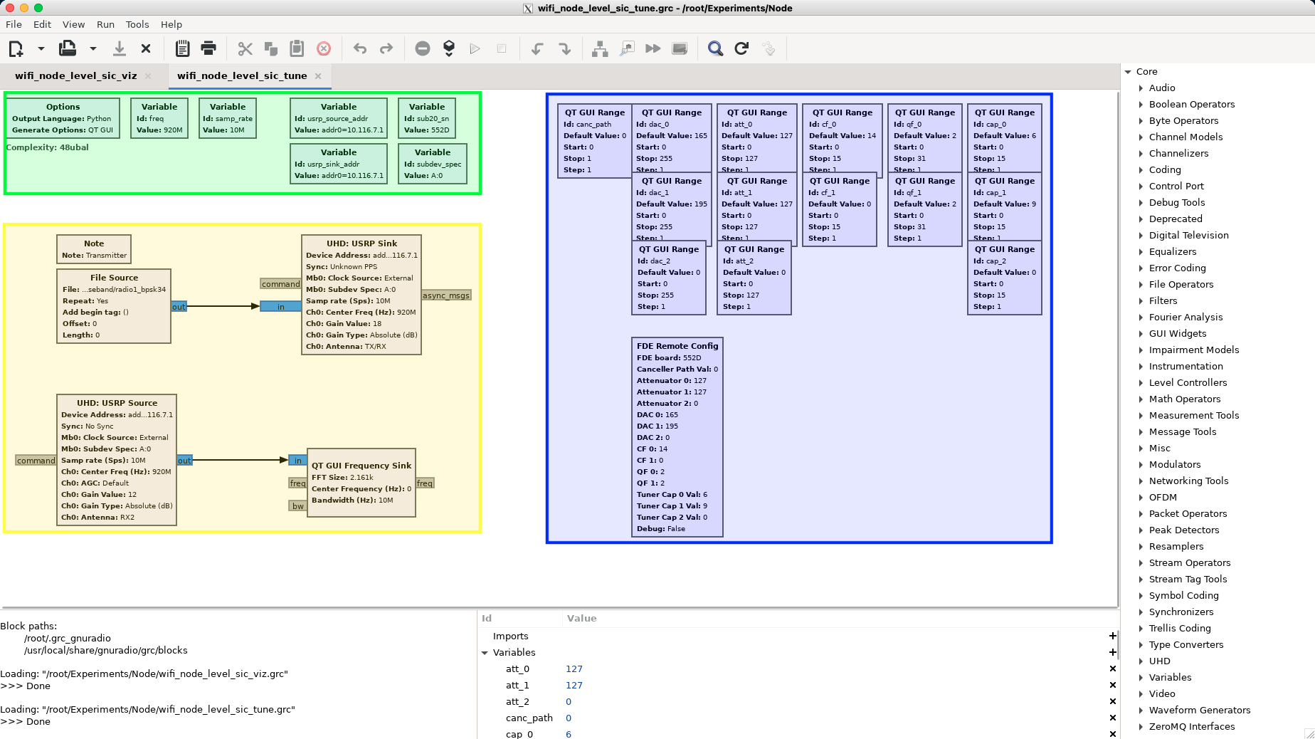
The flowgraph has three main functional sections:
- Green (variables):
freq(center frequency, default 920 MHz),samp_rate(bandwidth),usrp_source_addr/usrp_sink_addr(USRP X310 IP address — should be identical for a single radio),subdev_spec(transceiver specifier),sub20_sn(SUB-20 serial number for the chosen radio/transceiver combination). See the radio connection details table below. - Blue (GUI sliders): FDE canceller configuration sliders. The "FDE Remote Config" block sends slider values to the SUB-20 device over the network to program the Gen-2 RF canceller PCB.
- Yellow (data flow): A "File Source" reads a complex baseband 802.11a-like signal (BPSK 3/4) and feeds it to the "USRP Sink" for transmission. The "USRP Source" produces the received signal, which is displayed by a "QT GUI Frequency Sink".
Before running, change the samp_rate variable to 20e6 (double-click the variable block and enter 20e6).
Press the play button to start the experiment.
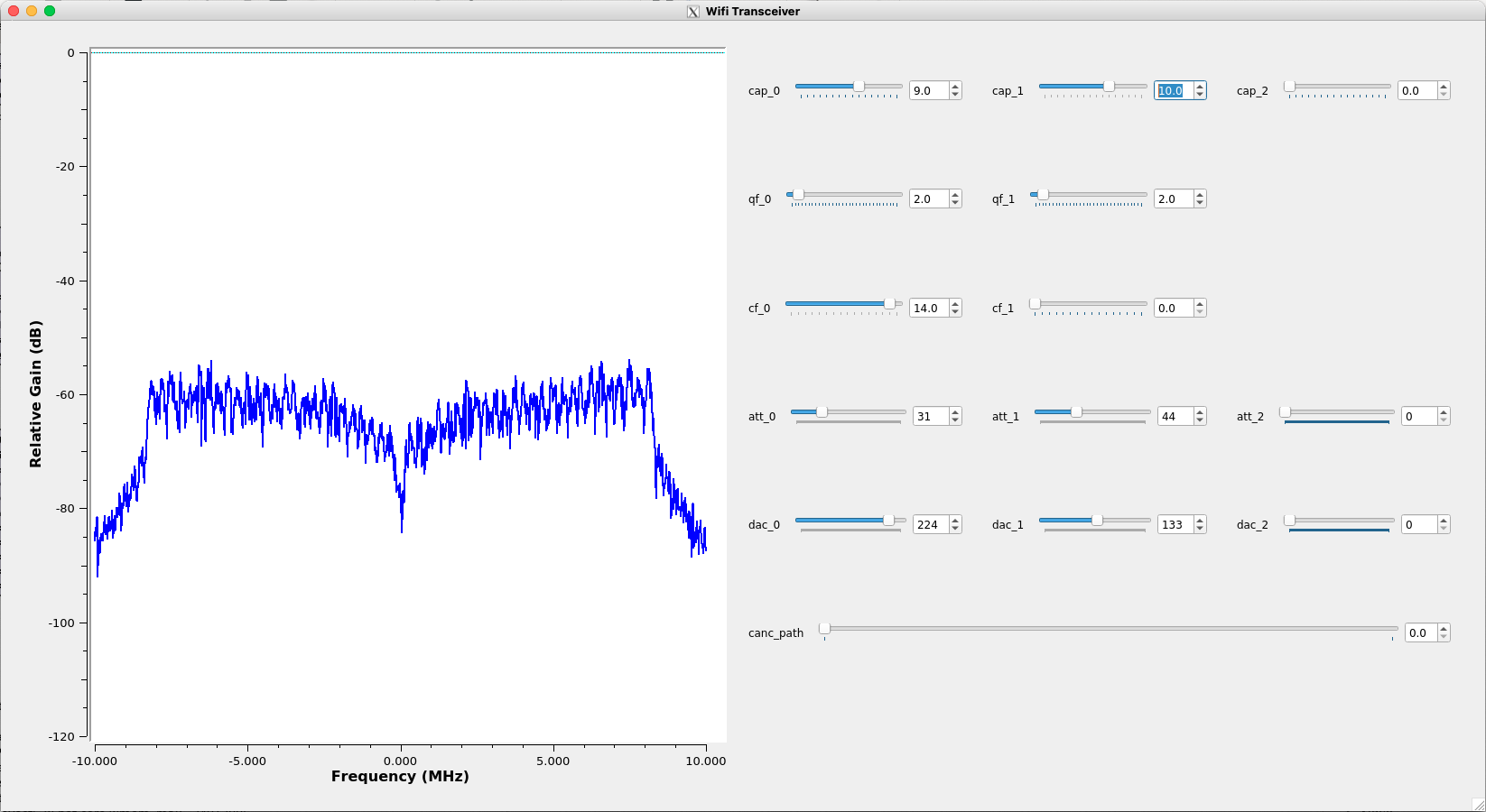
The GUI shows the power spectrum of the self-interference (SI) signal after RF SIC. The goal is to minimize the SI power using the configuration sliders.
Important: Do not drag sliders — this sends many configuration requests to the SUB-20. Enter values by clicking the number next to each slider, or clicking along the slider track to step through values.
Radio connection details:
| Radio # | USRP Address | Subdevice | SUB-20 Serial # |
|---|---|---|---|
| 1 | 10.113.2.71 | A:0 | 552D |
| 2 | 10.113.2.71 | B:0 | 5647 |
| 3 | 10.113.2.72 | A:0 | 552C |
| 4 | 10.113.2.72 | B:0 | 18A1 |
Initial canceller configuration values:
| Radio # | cap_0 |
cap_1 |
cap_2 |
qf_0 |
qf_1 |
cf_0 |
cf_1 |
att_0 |
att_1 |
dac_0 |
dac_1 |
|---|---|---|---|---|---|---|---|---|---|---|---|
| 1 | 9 | 10 | 0 | 2 | 2 | 14 | 0 | 60 | 55 | 86 | 107 |
| 2 | 4 | 10 | 0 | 0 | 0 | 2 | 7 | 2 | 13 | 201 | 161 |
| 3 | 3 | 8 | 0 | 2 | 2 | 0 | 0 | 22 | 91 | 105 | 22 |
| 4 | 5 | 3 | 0 | 2 | 2 | 8 | 6 | 11 | 19 | 159 | 155 |
Any parameter not listed should be set to 0.
Parameter meanings:
cap_0, cap_1, cap_2— antenna tuner controlatt_0, att_1— attenuator for FDE tap 0 and tap 1 (higher = greater attenuation)dac_0, dac_1— phase shifter for FDE tap 0 and tap 1cf_0, cf_1— center frequency for FDE tap 0 and tap 1 (higher = lower center frequency)qf_0, qf_1— quality factor for FDE tap 0 and tap 1 (higher = lower quality factor)canc_path— canceller path:0= wideband FDE,1= narrowband Gen-1att_2— attenuator for the Gen-1 pathdac_2— phase shifter for the Gen-1 path
¶ Step 2 — Visualize Node-Level FD Performance with wifi_node_level_sic_viz
Open the visualization flowgraph in GNU Radio:
~/Experiments/Node/wifi_node_level_sic_viz.grc
Set samp_rate to 20e6, then press the play button.
This flowgraph transmits 802.11a packets with QPSK 3/4 modulation.
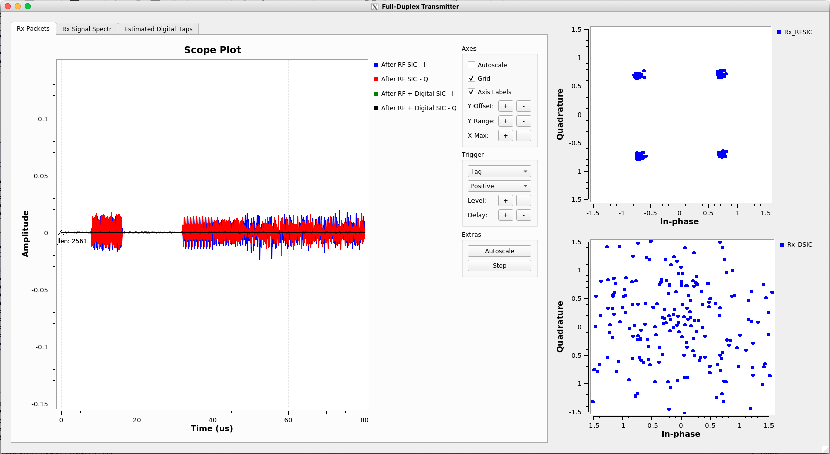
The GUI shows:
- After RF SIC: The self-interference is still present and decodable (clear QPSK constellation).
- After digital SIC: The digital baseband cancellation drives the SI to the noise floor (noisy constellation, time-domain signal at noise floor).
¶ Step 3 — Configure the Other Radios
Repeat Steps 1 and 2 with different values of usrp_source_addr/usrp_sink_addr, subdev_spec, and sub20_sn to configure and benchmark each of the four FD radios (see the tables in Step 1).
Manual tuning strategy if initial values do not give ideal cancellation:
- Adjust
dac_0anddac_1first to see if residual SI power drops. - If not, adjust
att_0andatt_1, then retunedac_0/dac_1. - For a full from-scratch configuration:
- Set
att_0andatt_1to127(turns off canceller). - Adjust
cap_0andcap_1until SI spectral power density is between -45 and -50 "dB". - Reduce
att_0incrementally; tunedac_0for the lowest SI. - Repeat with
att_1/dac_1; iterate between the two taps for best result.
- Set
¶ Part 2 — Gen-1 Narrowband Canceller (ORBIT Grid)
¶ Step 1 — Set Initial Canceller Configuration
On node11-10, run the initial canceller configuration:
cd flexicon_orbit/fd_transceiver_simple/sub20
./rf_canc_gen1_config 0 127 16 6 6
Expected output:
Started...
Sub20 device found... Serial Number is 48AB
Device Opened!
...Finished programming DAC with value 0!
...Finished programming ATT with value 127!
...Finished programming CAP1 with value 16!
...Finished programming CAP2 with value 6!
...Finished programming CAP3 with value 6!
The arguments are: PS-CODE ATT-CODE C1-CODE C2-CODE C3-CODE
PS-CODE(0–255): 8-bit phase shifterATT-CODE(0–127): 7-bit attenuator (127 = canceller effectively off)C1-CODE, C2-CODE, C3-CODE: capacitor codes;16 6 6provides ~20 dB isolation from the antenna-circulator interface
¶ Step 2 — Run the GNU Radio Experiment (node_level_sic_fd_gui)
GNU Radio experiments are located at ~/flexicon_orbit/experiments/grc/. Open GNU Radio and load the experiment:
gnuradio-companion &
Open node_level_sic_fd_gui.grc.
Tunable variables:
freq— carrier frequency (Gen-1 hardware supports approximately 900–1000 MHz)samp_rate— bandwidth (recommend no more than 5 MHz for the narrowband canceller)
This experiment visualizes:
- Received self-interference after RF SIC and after digital SIC
- Received power spectra after RF SIC and after digital SIC
- Complex-valued digital SIC filter taps
- Estimated SI channel
Use a second terminal window to configure the Gen-1 canceller PCB while the flowgraph is running (see Step 3 below).
¶ Step 3 — Run the UHD Experiment (fd_transceiver_simple) — Terminal 1
Open a terminal on node11-10. Run the full-duplex transceiver experiment:
cd ~/flexicon_orbit/fd_transceiver_simple/uhd/build/
./fd_transceiver_simple --tx-args="serial=F331D4" --rx-args="serial=F331D4" --rate 1e6 --freq 900e6 --tx-gain 0 --rx-gain 10
Expected output (example):
linux; GNU C++ version 4.8.4; Boost_105400; UHD_003.010.001.001-0-unknown

Creating the transmit usrp device with: serial=F331D4...
-- Opening a USRP2/N-Series device...
-- Current recv frame size: 1472 bytes
-- Current send frame size: 1472 bytes

.
.
.

Press Ctrl + C to stop streaming...

TX Stream time was: 0 full secs, 0.100064 frac secs

RX Signal Power: -44.093768 dBm (N_FFt = 2048)
RX Res Signal Power: -98.570747 dBm (N_fft = 1024)
Amount of Digital SIC: 54.476979 dB

RX Signal Power: -44.232740 dBm (N_FFt = 2048)
RX Res Signal Power: -98.113147 dBm (N_fft = 1024)
Amount of Digital SIC: 53.880407 dB

RX Signal Power: -43.959299 dBm (N_FFt = 2048)
RX Res Signal Power: -93.406544 dBm (N_fft = 1024)
Amount of Digital SIC: 49.447245 dB

RX Signal Power: -44.179891 dBm (N_FFt = 2048)
RX Res Signal Power: -101.593147 dBm (N_fft = 1024)
Amount of Digital SIC: 57.413256 dB
The default sine wave has amplitude ampl=0.3 and wave-freq=100e3 (100 kHz), corresponding to ~0 dBm TX power. The output shows RX signal power, residual SI after digital cancellation, and the total digital SIC achieved. The UHD program is calibrated with --rx-gain=10; other RX gain values may result in inaccurate power level computation.
In this example, ~90 dB total SIC is achieved: ~45 dB from the Gen-1 RF canceller and ~50 dB from digital cancellation.
¶ Step 4 — Tune the Gen-1 Canceller — Terminal 2
In a second terminal on node11-10, check the SUB-20 connection:
lsusb
You should see an XDIMAX device connected to the USB hub.
Program the RF canceller with desired values:
cd ~/flexicon_orbit/fd_transceiver_simple/sub20/
./rf_canc_gen1_config PS-CODE ATT-CODE C1-CODE C2-CODE C3-CODE
Example (a known good configuration):
./rf_canc_gen1_config 110 30 16 6 6
Expected output:
Started...
Sub20 device found... Serial Number is 48AB
Device Opened!
...Finished programming DAC with value 110!
...Finished programming ATT with value 30!
...Finished programming CAP1 with value 16!
...Finished programming CAP2 with value 6!
...Finished programming CAP3 with value 6!
Adjust PS-CODE (phase) and ATT-CODE (attenuation) while observing Terminal 1 to minimize residual SI power. Keep C1=16, C2=6, C3=6 for stable antenna-circulator isolation.
¶ Step 5 (Optional) — Add a Secondary Transmitter on node13-8
From a third terminal on the ORBIT console, set up node13-8 as a secondary transmitter:
omf tell -a offh -t node13-8
omf load -i baseline-sdr.ndz -t node13-8
omf tell -a on -t node13-8
ssh root@node13-8
On node13-8, configure the USRP interface:
ifconfig eth2 192.168.10.1 netmask 255.255.255.0 up
Transmit a sine wave at a different frequency (e.g., 200 kHz) than the FD node's self-interference tone (100 kHz):
./tx_waveforms --args="serial=F331D4" --rate 1e6 --freq 900e6 --gain 10 --wave-type SINE --wave-freq 200e3
Observing the RX baseband at node11-10, you will see the 200 kHz tone from node13-8 in the received signal while the 100 kHz self-interference tone is cancelled to the USRP noise floor (~-90 dBm).
This secondary transmitter can also be used while the node_level_sic_fd_gui GNU Radio flowgraph is running.
¶ Verification
Part 1 (COSMOS sb2):
- The
wifi_node_level_sic_tuneGUI displays the SI power spectrum and responds to slider changes (power level shifts when canceller parameters are adjusted). - After a good configuration, the
wifi_node_level_sic_vizflowgraph shows a clean QPSK constellation after RF SIC, and a noisy/flat constellation (SI at noise floor) after digital SIC. - The time-domain signal (black line in the GUI) sits at the noise floor after digital SIC.
Part 2 (ORBIT grid):
uhd_find_devicesreturns the USRP N210 with serialF331D4.- The
fd_transceiver_simpleoutput shows "Amount of Digital SIC" values around 50–55 dB, and total SIC of ~90 dB. - When the optional
node13-8secondary transmitter is active, its tone is visible in the RX baseband while the FD node's own self-interference is suppressed.
¶ Cleanup
¶ Saving Your Work (Optional — allow 30+ minutes)
If you modified the experiment and want to save your image for next time:
-
From the server/node, exit to the console:
exit -
Reboot the server/node to ensure a clean state for imaging (COSMOS example):
omf tell -a reboot -t srv2-lg1Wait a few minutes for it to come back online, then log back in:
ssh -X root@srv2-lg1 -
Run the prepare script (ignore warnings):
./prepare.shNote the
omf savecommand output by this script. -
Exit back to the console and run the save command (takes 5–10 minutes):
omf save -n srv2-lg1.sb2.cosmos-lab.orgConfirm output similar to:
INFO exp: INFO exp: - Saving process started at: 2023-03-21 04:33:09 +0000 INFO exp: (this may take a while depending on the size of your image) INFO exp: - Saving disk image of 'srv2-lg1.sb2.cosmos-lab.org' finished with success. INFO exp: - Saving process completed at: 2023-03-21 04:35:49 +0000 INFO exp:The saved filename appears in the
omf saveoutput, e.g.:INFO srv2-lg1.sb2.cosmos-lab.org: INFO srv2-lg1.sb2.cosmos-lab.org: - Saving image of '/dev/sda' on node 'srv2-lg1.sb2.cosmos-lab.org' INFO srv2-lg1.sb2.cosmos-lab.org: to the file 'mpk2138-node-srv2-lg1.sb2.cosmos-lab.org-2023-03-21-04-32-59.ndz' on host '10.113.2.40' INFO srv2-lg1.sb2.cosmos-lab.org:Keep note of this filename. Use it instead of
flexicon-cosmos-v1.ndzon your next session. -
Optionally rename the saved image (keep your COSMOS username as a prefix; no spaces):
mv /export/omf-images-5.4/mpk2138-node-srv2-lg1.sb2.cosmos-lab.org-2023-03-21-04-32-59.ndz /export/omf-images-5.4/mpk2138-IMAGE-NAME-HERE.ndz
¶ Release Resources
From the sandbox console, power off the resource:
omf tell -a offh -t srv2-lg1
For ORBIT (Part 2):
omf tell -a offh -t node11-10
omf tell -a offh -t node13-8
¶ Troubleshooting
| Symptom | Likely cause | Fix |
|---|---|---|
omf tell or omf load returns Reply: ERROR (NOT REGISTERED) |
Node not registered with the OMF AM | Run the command again; it should succeed on retry |
omf load timed out |
Image too large for the default timeout | Re-run with a longer timeout: omf load -o 3600 -i flexicon-cosmos-v1.ndz -t srv2-lg1 |
omf save failed |
Transient error during imaging | Re-run the command; if it fails more than three times, contact the authors |
| GNU Radio flowgraph exits with error code -11 | GRC runtime crash | Re-run the flowgraph; if it persists, restart the tutorial from the beginning |
| "Device not found" when running GNU Radio flowgraph | USRP X310 is unresponsive or disconnected from the COSMOS network | Not user-resolvable via console; contact Manav Kohli (mpk2138[at]columbia.edu) |
Sliders in wifi_node_level_sic_tune have no effect |
Wrong USRP address, subdevice spec, or SUB-20 serial number | Double-check the combination against the radio connection details table |
wifi_node_level_sic_viz shows residual signal in bottom constellation |
Initial configuration values are off due to environmental changes | Adjust dac_0/dac_1 first; then att_0/att_1; see the manual tuning strategy in Instructions |
| X11 forwarding fails; GNU Radio GUI won't open | -X flag not set or X11 not available on client |
Ensure SSH was launched with ssh -X (or -Y on macOS); install an X server on your local machine if needed |
uhd_find_devices returns no devices (ORBIT) |
USRP Ethernet interface not configured | Run ifconfig eth2 192.168.10.1 netmask 255.255.255.0 up and retry |
¶ References
- FlexICoN GitHub repository
- gr-fullduplex OOT module README
- Columbia FlexICoN project
- SUB-20 USB adapter — user manual
- Manav Kohli et al., "Open-access full-duplex wireless in the ORBIT and COSMOS testbeds," Computer Networks, no. 199, p. 108420, Nov. 2021 — (Download)
- Tingjun Chen et al., "Wideband Full-Duplex Wireless via Frequency-Domain Equalization: Design and Experimentation," ACM MobiCom'19, Oct. 2019 — (Download)
- Manav Kohli et al., "Open-access full-duplex wireless in the ORBIT and COSMOS testbeds," ACM MobiCom'20 WiNTECH Workshop, Sept. 2020 — (Download)
- Make a reservation
- SSH access guide
- OMF commands reference
Author(s): COSMOS team (Manav Kohli, Columbia University; Tingjun Chen, Duke University) · Last verified: Not re-tested (migrated 2026-06-20) · Tested image/release: flexicon-cosmos-v1.ndz / flexicon-orbit-v4.ndz · Tags: full-duplex, sdr, gnu-radio, uhd, flexicon, self-interference-cancellation, usrp