¶ Analog FM Transmission Over FR3
Transmit an analog FM signal end-to-end over FR3 (millimeter-wave) bands using a USRP-2974 (Krypton) paired with Pi-Radio FR3 front-ends, then receive and demodulate it on a second USRP-2974 — all orchestrated from GNU Radio flowgraphs.
¶ Overview
This tutorial demonstrates an analog FM transmission path that spans the FR3 spectrum. A GNU Radio FM transmitter flowgraph runs on a USRP-2974 (Krypton) and outputs an IF signal at 1.5 GHz. A Pi-Radio FR3 front-end up-converts this to 10 GHz for over-the-air transmission via Vivaldi antennas. On the receive side, a second Pi-Radio front-end down-converts the 10 GHz signal back to 1.5 GHz, where a second USRP-2974 runs a GNU Radio FM receiver flowgraph to recover the audio baseband.
The Pi-Radio web UI (port 5006 on the rfdev-* nodes) is used to configure the LO frequencies for each front-end. This experiment exercises the full FR3 hardware stack in COSMOS Sandbox 1 and serves as the entry point for all subsequent FR3 tutorials.
¶ Learning outcomes
After completing this tutorial you will be able to:
- Configure Pi-Radio FR3 front-ends via the web UI (LO frequency panel).
- Run a GNU Radio FM transmitter flowgraph on a USRP-2974 (Krypton).
- Run a GNU Radio FM receiver flowgraph on a second USRP-2974.
- Verify an end-to-end FR3 analog link at ~10 GHz.
¶ At a glance
| Difficulty | Intermediate |
| Estimated time | TODO: verify |
| Domain / sandbox | sb1.cosmos-lab.org |
| Topic group | FR3 |
| Last verified | Not re-tested (migrated 2026-06-20) |
¶ Prerequisites
Background knowledge
- Familiarity with the USRP-2974 (Krypton): embedded X310, 10 MHz–6 GHz, 160 MHz BW.
- Basic GNU Radio flowgraph operation.
- FR3 hardware overview — see the FR3 hardware pages on this wiki.
Account & access
- A COSMOS account — register here.
- An approved reservation on sb1.cosmos-lab.org with FR3 hardware access — see Make a reservation.
- SSH access to the domain console — see SSH access.
- Browser access to the Pi-Radio web UI on the rfdev-* nodes (port 5006).
¶ Resources required
Devices / nodes
| Resource | Role | Qty | Notes |
|---|---|---|---|
| sdr1-piradio | FM transmitter (USRP-2974 / Krypton) | 1 | Runs GNU Radio FM TX flowgraph; IF output at 1.5 GHz |
| sdr2-piradio | FM receiver (USRP-2974 / Krypton) | 1 | Runs GNU Radio FM RX flowgraph; IF input at 1.5 GHz |
| rfdev-sdr1-piradio | Tx Pi-Radio FR3 front-end | 1 | Up-converts 1.5 GHz IF → ~10 GHz RF; configured via web UI port 5006 |
| rfdev-sdr2-piradio | Rx Pi-Radio FR3 front-end | 1 | Down-converts ~10 GHz RF → 1.5 GHz IF; configured via web UI port 5006 |
Disk images
| Image | Load onto | Provides |
|---|---|---|
| fr3-tutorials.ndz | sdr1-piradio, sdr2-piradio | GNU Radio FM TX/RX flowgraphs + UHD for USRP-2974 |
Software components
| Component | Version | Source |
|---|---|---|
| GNU Radio | TODO: verify | preinstalled in fr3-tutorials.ndz |
| UHD (USRP Hardware Driver) | TODO: verify | preinstalled in fr3-tutorials.ndz |
| Pi-Radio web UI | TODO: verify | embedded in rfdev-* nodes (port 5006) |
Spectrum / RF / special
- 2× Vivaldi antennas (Tx and Rx) connected to the Pi-Radio FR3 front-ends. See the FR3 hardware pages for antenna layout.
- Example RF frequency: ~10 GHz (High LO = 10 GHz, Low LO = 1.5 GHz IF). Exact placement depends on mixer sign/path; verify with your reservation's allowed spectrum.
¶ Topology
Two USRP-2974 (Krypton) nodes each paired with a Pi-Radio FR3 front-end. The control plane uses the standard COSMOS console; the RF path is: USRP-2974 (sdr1) → Pi-Radio FR3 Tx (rfdev-sdr1) → Vivaldi Tx antenna → over-the-air at ~10 GHz → Vivaldi Rx antenna → Pi-Radio FR3 Rx (rfdev-sdr2) → USRP-2974 (sdr2). The Pi-Radio web UI for each rfdev is accessible via a browser from the console or a forwarded port.
¶ Setup
- Reserve sb1.cosmos-lab.org with FR3 resources and log into the console:
ssh <username>@console.sb1.cosmos-lab.org - Turn all resources off before imaging:
omf tell -a offh -t system:topo:allres - Load the FR3 tutorials image onto the USRP nodes:
omf load -i fr3-tutorials.ndz -t sdr1-piradio,sdr2-piradio - Turn the nodes on and confirm they are up:
omf tell -a on -t sdr1-piradio,sdr2-piradio omf stat -t sdr1-piradio,sdr2-piradio - Complete the FR3 hardware setup steps (shared procedure) — see the FR3 Setup guide.
¶ Instructions
¶ Step 1 — Configure the Pi-Radio FR3 front-ends
Open a browser and navigate to the Pi-Radio web UI on each rfdev node at port 5006.
For the Tx front-end (rfdev-sdr1-piradio), open the Frequency panel and set:
- Low LO Frequency (GHz):
1.200000 - High LO Frequency (GHz):
10.000000
Set the low-side LO 300 MHz below the IF, not equal to it. This is the single most consequential setting on the chain. The front-end mixes the incoming IF down by its low-side LO and back up by its high-side LO:
RF = high_lo + (IF - low_lo)
With low_lo at 1.2 GHz and a 1.5 GHz IF the signal radiates at 10.3 GHz. With low_lo equal to the IF it would radiate at 10 GHz — and the centre of your signal would land at baseband inside the front-end, exactly where the front-end's own LO leakage sits. Measured on this chain at 20 MSps, relative to the noise floor, with the transmitter switched off:
| frequency plan | leakage at DC (±150 kHz) |
|---|---|
IF 1.5 GHz, low_lo 1.5 GHz (equal) |
+34.9 dB |
IF 1.5 GHz, low_lo 1.2 GHz (offset) |
+20.1 dB |
That spike is unchanged when the transmitter is off, which is what identifies it as leakage rather than signal. The offset removes about 15 dB of it from the middle of your band, and a matched measurement showed the wanted tone unchanged (+47.7 dB against +45.9 dB — within run-to-run variation). There is no cost to paying it, so pay it always.
Measure this with UHD's automatic DC-offset correction switched off (
usrp.set_rx_dc_offset(False, 0)), or you will not measure it at all. That correction is a tracking loop: leave it on and it progressively removes the DC term, giving readings that fall by 7 dB over a single session and a 9 dB spread across identical runs. With it off the same measurement repeats to 0.1 dB. An earlier revision of this page quoted +3.0 dB for the offset case and a 31.5 dB benefit; those were taken with the loop active and are corrected above.
For the Rx front-end (rfdev-sdr2-piradio), open the Frequency panel and set:
- Low LO Frequency (GHz):
1.200000 - High LO Frequency (GHz):
10.000000
Identical on both front-ends — a mismatch between them is the classic dead-link-that-looks-like- broken-hardware.
The front-end mixes the incoming IF down by its low-side LO and back up by its high-side LO:
RF = high_lo + (IF − low_lo)
so with a 1.5 GHz IF against a 1.5 GHz low-side LO the RF lands at the high-side LO, 10 GHz. (Older revisions of this page said "exact placement depends on mixer sign/paths"; the relation above was confirmed by measurement on 2026-07-30.)
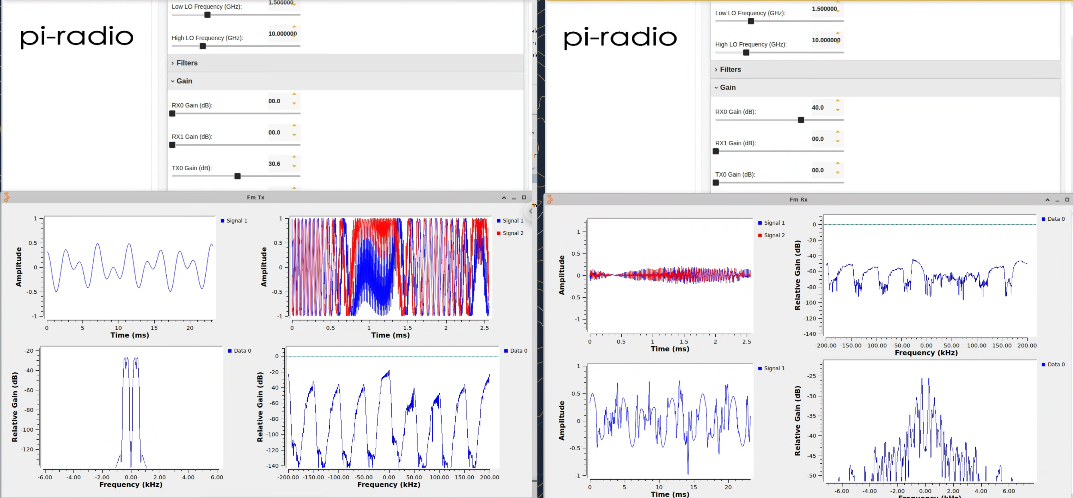
The screenshot below shows the settings used in the original demo. Leave Filters, Gain (except where noted), and LO Suppression at defaults for the first run.
¶ Why this matters more for FM than for a tone
An FM signal is centred on the IF. The sine tutorial puts its tone 5 MHz off centre and so steps around the leakage even on the old equal-LO plan; an FM channel has nothing to step around with, and lands right on top of it. That is why the offset is not optional here.
Honest scope: the leakage numbers are measured, including the fact that the spike is unchanged with the transmitter off. The FM audio path itself was not re-run end to end under the offset plan — the screenshots below were taken on the older equal-LO settings, so their Low LO field reads 1.500000. The RF moves from 10 GHz to 10.3 GHz; nothing else in the procedure changes.
¶ Step 2 — Run the GNU Radio FM transmitter
SSH from the console to the transmitter node:
ssh root@sdr1-piradio
Launch the GNU Radio FM transmitter flowgraph (example path — verify against the image):
root@sdr1-piradio:~# gnuradio-companion grc-fm-tx.grc
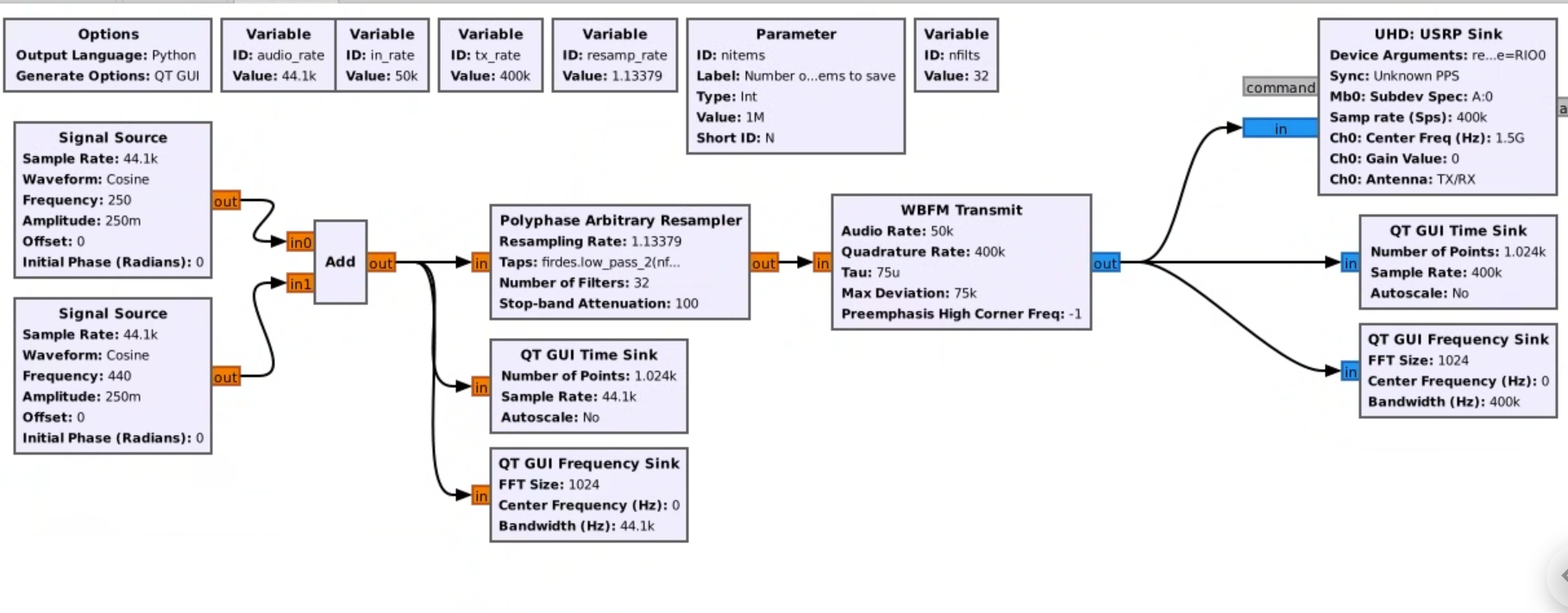
The flowgraph generates an FM-modulated signal at 1.5 GHz IF, which is fed to the Pi-Radio Tx front-end for up-conversion to ~10 GHz.
¶ Step 3 — Run the GNU Radio FM receiver
Open a second SSH session from the console to the receiver node:
ssh root@sdr2-piradio
Launch the GNU Radio FM receiver flowgraph (example path — verify against the image):
root@sdr2-piradio:~# gnuradio-companion grc-fm-rx.grc
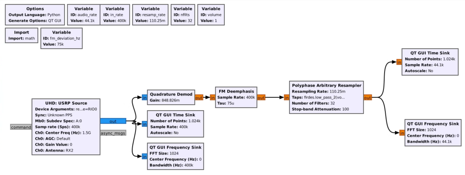
The flowgraph receives the 1.5 GHz IF from the Pi-Radio Rx front-end and FM-demodulates it to recover the audio baseband.
¶ Verification
- The Pi-Radio web UI on both rfdev nodes shows the LO frequencies locked at 1.5 GHz (Low) and 10 GHz (High).
- The GNU Radio FM transmitter flowgraph runs without errors on sdr1-piradio.
- The GNU Radio FM receiver flowgraph on sdr2-piradio shows a received signal and demodulated audio output.
¶ Cleanup
omf tell -a offh -t system:topo:allres
(No omf save needed unless you modified the image.)
¶ Troubleshooting
| Symptom | Likely cause | Fix |
|---|---|---|
| Pi-Radio web UI not reachable at port 5006 | Network routing or rfdev node not booted | Verify the rfdev-* node is powered and reachable from the console; check port forwarding if accessing from outside the sandbox |
| GNU Radio flowgraph fails to start | UHD device not found or wrong IP | Confirm sdr1-piradio/sdr2-piradio are booted with fr3-tutorials.ndz and the USRP-2974 is accessible via UHD |
| No signal at receiver | LO frequencies mismatched between Tx and Rx Pi-Radio front-ends | Verify both rfdev nodes have identical Low LO (1.200000 GHz) and High LO (10.000000 GHz) settings — a mismatch between the two front-ends is the usual cause |
| Weak or noisy received signal | Antenna alignment or gain settings | Check Vivaldi antenna orientation per FR3 hardware page; adjust gain in the Pi-Radio web UI |
¶ References
- Pi-Radio website
- GNU Radio
- FR3 hardware pages
- FR3 Setup guide
- Available SDR hardware
- Make a reservation
- SSH access
Author(s): COSMOS team · Frequency plan re-verified: 2026-07-30 (LO-leakage measurement above) · Last verified: Not re-tested (migrated 2026-06-20) · Tested image/release: fr3-tutorials.ndz · Tags: fr3, sdr, gnuradio, fm, pi-radio, usrp-2974, krypton, millimeter-wave