¶ Generating and Observing a Basic FR3 Sine Wave
Transmit a single-tone sine IF at 1.5 GHz from a USRP-2974 through a Pi-Radio FR3 front-end up-converting to 10.3 GHz over the air, then down-convert on the receive side and verify the tone with an ASCII DFT spectrum viewer.
¶ Overview
This tutorial exercises the Pi-Radio FR3 (Frequency Range 3) millimeter-wave front-ends available in COSMOS Sandbox 1. A USRP-2974 (Krypton — embedded X310, 10 MHz–6 GHz, 160 MHz BW) generates a 1.5 GHz IF carrying a 5 MHz baseband sine. A Pi-Radio front-end up-converts that IF to an FR3 carrier (~10 GHz) and transmits it over the air. A second Pi-Radio front-end receives the signal and down-converts it back to 1.5 GHz, where a second USRP-2974 running rx_ascii_art_dft confirms the tone.
The Pi-Radio web UI (running on the rfdev-* nodes at port 5006) is used to configure the LO frequencies for both front-ends.
This is a minimal "hello-world" experiment for the FR3 chain: no GNU Radio flowgraph, no additional signal processing — just a tone through the hardware.
¶ Learning outcomes
After completing this tutorial you will be able to:
- Configure Pi-Radio FR3 front-ends via the web UI (Low LO / High LO frequency settings).
- Transmit a tone with
tx_waveformson a USRP-2974 using the RIO0 PCIe path. - Observe a received tone with
rx_ascii_art_dfton a second USRP-2974. - Verify an end-to-end FR3 over-the-air link.
¶ At a glance
| Difficulty | Intermediate |
| Estimated time | 45 min |
| Domain / sandbox | sb1.cosmos-lab.org (FR3 Pi-Radio nodes) |
| Topic group | FR3 |
| Last verified | Not re-tested (migrated 2026-06-20) |
¶ Prerequisites
Background knowledge
- Familiarity with the USRP-2974 (Krypton) and its embedded X310 radio accessed via
resource=RIO0. - Basic RF concepts (carrier, IF, LO, up/down conversion).
- The six-step experiment life cycle.
Account & access
- A COSMOS account — register here.
- An approved reservation on sb1.cosmos-lab.org with the FR3 Pi-Radio nodes — see Make a reservation.
- SSH access to the console — see SSH access.
- Browser access to the Pi-Radio web UI on the
rfdev-*nodes at port 5006 (reachable through the console or a tunnel).
¶ Resources required
Devices / nodes
| Resource | Role | Qty | Notes |
|---|---|---|---|
| sdr1-piradio | Transmit host (USRP-2974) | 1 | Embedded X310; radio accessed as resource=RIO0 |
| sdr2-piradio | Receive host (USRP-2974) | 1 | Embedded X310; radio accessed as resource=RIO0 |
| rfdev-sdr1-piradio | Transmit Pi-Radio FR3 front-end | 1 | Web UI on port 5006; provides up-conversion to FR3 carrier |
| rfdev-sdr2-piradio | Receive Pi-Radio FR3 front-end | 1 | Web UI on port 5006; provides down-conversion from FR3 carrier |
Disk images
| Image | Load onto | Provides |
|---|---|---|
| fr3-tutorials.ndz | sdr1-piradio, sdr2-piradio | UHD with RIO0 support; FR3 tutorial tools preinstalled |
Software components
| Component | Version | Source |
|---|---|---|
| UHD (USRP Hardware Driver) | TODO: verify | preinstalled in fr3-tutorials.ndz |
| tx_waveforms | TODO: verify | preinstalled in fr3-tutorials.ndz |
| rx_ascii_art_dft | TODO: verify | preinstalled in fr3-tutorials.ndz |
| Pi-Radio web UI | TODO: verify | running on rfdev-* nodes at port 5006 |
Spectrum / RF / special
- 2× Vivaldi antennas (Tx and Rx) connected to the Pi-Radio front-ends. See the FR3 hardware pages for antenna layout.
- The example uses a ~10 GHz RF carrier (FR3 band). Stay within your reservation's allowed spectrum.
- TX gain: 30 dB on sdr1-piradio; RX gain: 30 dB on sdr2-piradio; all other Pi-Radio UI gains set to 0.
¶ Topology
Two USRP-2974 hosts (sdr1-piradio and sdr2-piradio) each connected to a Pi-Radio FR3 front-end (rfdev-sdr1-piradio and rfdev-sdr2-piradio) via RF cables. The front-ends transmit and receive over the air using Vivaldi antennas.
sdr1-piradio→rfdev-sdr1-piradio(Pi-Radio Tx FE) → antenna → air- air → antenna →
rfdev-sdr2-piradio(Pi-Radio Rx FE) →sdr2-piradio
Both Pi-Radio front-ends are configured via their web UIs (port 5006) to use Low LO = 1.2 GHz and High LO = 10 GHz, placing the RF at 10.3 GHz.
¶ Setup
- Reserve the FR3 Pi-Radio resources in sb1.cosmos-lab.org and log into the console:
ssh <username>@console.sb1.cosmos-lab.org - Turn off all resources before imaging:
omf tell -a offh -t sdr1-piradio,sdr2-piradio,rfdev-sdr1-piradio,rfdev-sdr2-piradio - Load the FR3 tutorials image onto the USRP hosts:
omf load -i fr3-tutorials.ndz -t sdr1-piradio,sdr2-piradio - Turn the nodes on and confirm they are up:
omf tell -a on -t sdr1-piradio,sdr2-piradio,rfdev-sdr1-piradio,rfdev-sdr2-piradio
omf stat -t sdr1-piradio,sdr2-piradio,rfdev-sdr1-piradio,rfdev-sdr2-piradio
See FR3 Setup for additional hardware-specific setup steps (included by the original tutorial via
[[Include(/UserGuide/FR3Setup)]]).
¶ Instructions
¶ Step 1 — Configure the Pi-Radio front-ends via the web UI
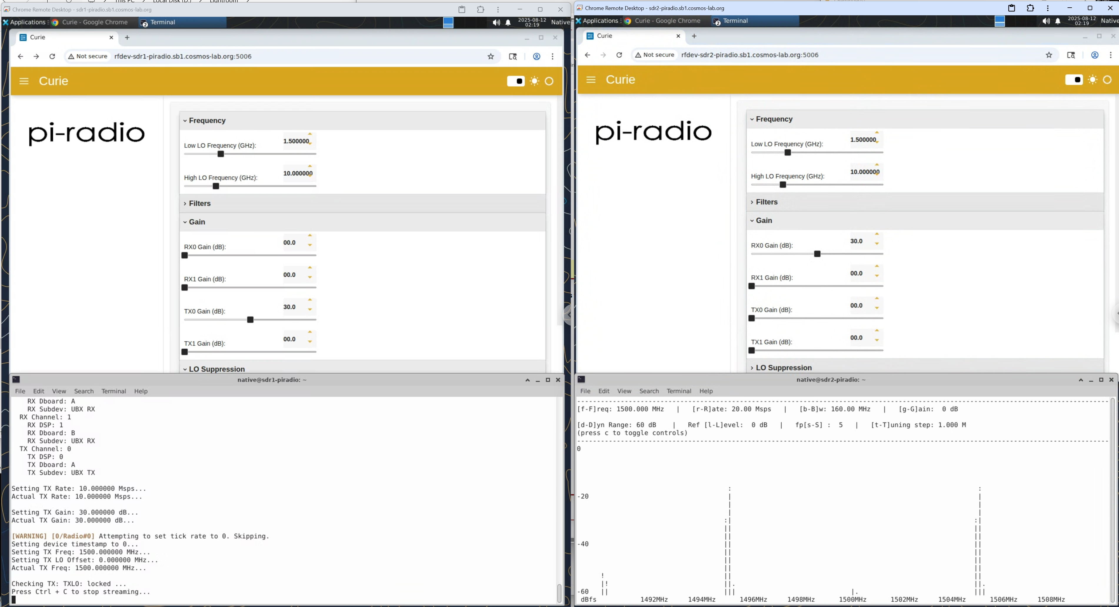
Open a browser and navigate to the Pi-Radio web UI for each front-end:
- Transmit front-end:
http://rfdev-sdr1-piradio:5006 - Receive front-end:
http://rfdev-sdr2-piradio:5006
On both front-ends, go to the Frequency panel and set:
- Low LO Frequency (GHz):
1.200000 - High LO Frequency (GHz):
10.000000
Set the low-side LO 300 MHz below the IF, not equal to it. This is the single most consequential setting on the chain. The front-end mixes the incoming IF down by its low-side LO and back up by its high-side LO:
RF = high_lo + (IF - low_lo)
With low_lo at 1.2 GHz and a 1.5 GHz IF the signal radiates at 10.3 GHz. With low_lo equal to the IF it would radiate at 10 GHz — and the centre of your signal would land at baseband inside the front-end, exactly where the front-end's own LO leakage sits. Measured on this chain at 20 MSps, relative to the noise floor, with the transmitter switched off:
| frequency plan | leakage at DC (±150 kHz) |
|---|---|
IF 1.5 GHz, low_lo 1.5 GHz (equal) |
+34.9 dB |
IF 1.5 GHz, low_lo 1.2 GHz (offset) |
+20.1 dB |
That spike is unchanged when the transmitter is off, which is what identifies it as leakage rather than signal. The offset removes about 15 dB of it from the middle of your band, and a matched measurement showed the wanted tone unchanged (+47.7 dB against +45.9 dB — within run-to-run variation). There is no cost to paying it, so pay it always.
Measure this with UHD's automatic DC-offset correction switched off (
usrp.set_rx_dc_offset(False, 0)), or you will not measure it at all. That correction is a tracking loop: leave it on and it progressively removes the DC term, giving readings that fall by 7 dB over a single session and a 9 dB spread across identical runs. With it off the same measurement repeats to 0.1 dB. An earlier revision of this page quoted +3.0 dB for the offset case and a 31.5 dB benefit; those were taken with the loop active and are corrected above.
The front-end mixes the incoming IF down by its low-side LO and back up by its high-side LO:
RF = high_lo + (IF − low_lo)
so with a 1.5 GHz IF against a 1.5 GHz low-side LO the RF lands at the high-side LO, 10 GHz. (Older revisions of this page said "exact placement depends on mixer sign/paths"; the relation above was confirmed by measurement on 2026-07-30.)
¶ Keep the baseband tone offset too
--wave-freq 5e6is load-bearing, not decorative, and it is a second line of defence behind the LO offset above. Measured withlow_loequal to the IF — the configuration this page used to recommend — at 20 MSps, relative to the noise floor:
DC (±150 kHz) tone at +5 MHz Transmitter off +34.5 dB +2.0 dB Transmitter on +34.6 dB +47.7 dB The spike at DC is unchanged when the transmitter is off — it is leakage, not your signal. The 5 MHz baseband offset puts the tone 13 dB above it and 45 dB above the floor, which is why this tutorial works. Set
--wave-freq 0and you will be looking at the front-end's LO leakage and calling it your carrier.With the offset plan now recommended above the DC spike is about +20 dB rather than +35 dB, so the 5 MHz baseband offset is still doing real work — keep it.
--wave-freq 0would put your tone on whatever leakage remains, and you would have no way to tell signal from artefact.Both measurements were taken on this chain on 2026-07-31, transmitting the exact
tx_waveformscommand in this tutorial.
Leave Filters, Gain (except where noted below), and LO Suppression at defaults for this first run.
Set the following gains in the Pi-Radio UI:
- TX Gain: 30 (on the rfdev-sdr1-piradio / Tx front-end)
- RX Gain: 30 (on the rfdev-sdr2-piradio / Rx front-end)
- All other gains: 0
¶ Step 2 — Transmit a sine wave from sdr1-piradio
Open an SSH session to the transmitter node from the console:
ssh root@sdr1-piradio
Start tx_waveforms with a 5 MHz baseband sine on a 1.5 GHz IF, 10 Msps, amplitude 0.7, TX gain 30 dB:
tx_waveforms --args "resource=RIO0" --subdev A:0 --freq 1.5e9 --ampl 0.7 --gain 30 --wave-type SINE --ant TX/RX --rate 10e6 --wave-freq 5e6
Leave this running in the background (or open a second terminal to the transmitter).
¶ Step 3 — Observe the received tone on sdr2-piradio
Open an SSH session to the receiver node from the console:
ssh root@sdr2-piradio
Start the ASCII DFT spectrum viewer tuned to the 1.5 GHz IF at 20 Msps:
rx_ascii_art_dft --args "resource=RIO0" --subdev A:0 --freq 1.5e9 --ant RX2 --rate 20e6
You should observe a stable, narrow spectral line near the configured 5 MHz offset (side-markers set by the viewer) in the DFT display.
¶ Verification
- The Pi-Radio web UIs on both
rfdev-sdr1-piradioandrfdev-sdr2-piradioshow Low LO = 1.5 GHz and High LO = 10 GHz applied. tx_waveformsonsdr1-piradiostreams without errors.rx_ascii_art_dftonsdr2-piradioshows a stable, narrow spectral line near the 5 MHz offset within the 1.5 GHz IF band.- Stopping
tx_waveforms(Ctrl-C) causes the spectral line to collapse to the noise floor.
¶ Cleanup
Stop the UHD programs on both nodes with Ctrl-C, then power down all resources:
omf tell -a offh -t sdr1-piradio,sdr2-piradio,rfdev-sdr1-piradio,rfdev-sdr2-piradio
(No omf save needed unless you customized the image.)
¶ Troubleshooting
| Symptom | Likely cause | Fix |
|---|---|---|
tx_waveforms / rx_ascii_art_dft cannot find RIO0 |
USRP-2974 PCIe path not initialized | Reboot the host node; confirm with uhd_find_devices --args "resource=RIO0" |
| No spectral line visible in ASCII DFT | Pi-Radio LO frequencies not applied, or gain mismatch | Verify web UI settings on both rfdev nodes; confirm TX gain=30 on Tx FE and RX gain=30 on Rx FE, all others=0 |
| ASCII DFT shows noise/distortion only | Vivaldi antenna alignment or cable issue | Check antenna connections and orientation per the FR3 hardware page |
| Cannot reach rfdev web UI at port 5006 | Node not powered on, or network path not set up | Confirm omf stat shows rfdev nodes up; check console routing |
¶ References
- Pi-Radio website
- FR3 Setup guide
- Available SDR / USRP hardware
- Six-step experiment life cycle
- OMF commands reference
Author(s): COSMOS team · Frequency plan re-verified: 2026-07-30 (LO-leakage measurement above) · Last verified: Not re-tested (migrated 2026-06-20) · Tested image/release: fr3-tutorials.ndz · Tags: fr3, pi-radio, usrp, sdr, sine, millimeter-wave