¶ OFDM BER Across Five Subcarrier Modulations (FR3 and FR1)
Measure bit-error-rate curves for an OFDM link at BPSK, QPSK, 8-PSK, 16-QAM and 64-QAM, moving the
operating point with transmit power. The primary target is the COSMOS FR3 up/down-conversion chain
in sandbox 1 — two USRP-2974 nodes and the two Pi-Radio front-ends they feed — and the identical
experiment runs unchanged on FR1 (sub-6 GHz) hardware — a plain USRP pair in any
sandbox — by turning the front-ends off.
¶ Overview
This page replaces the earlier OFDM Transmission Over FR3 demo. That page showed a signal arriving;
this one measures how good it is across the whole modulation family, and corrects a frequency-plan
setting that quietly cost about 20 dB (see Set the frequency plan below).
Four devices, wired to each other, and sandbox 1 has exactly one set:
sdr1-piradio  ──IF──▶  rfdev-sdr1-piradio  ──))) 10.3 GHz OTA (((──  rfdev-sdr2-piradio  ──IF──▶  sdr2-piradio
 USRP-2974              Pi-Radio FR3 up                              Pi-Radio FR3 down            USRP-2974
The USRPs generate and capture OFDM at an intermediate frequency; the Pi-Radio front-ends translate
between that IF and FR3. BER is measured against a known repeating payload.
Why transmit power, and not injected noise. There are three ways to walk an operating point across
a waterfall, and only one of them reaches far enough here. Injected noise adds to the thermal noise
already present, so the effective SNR is signal / (injected + thermal) and it asymptotes to the
link's own margin over thermal — ask for more than the link has and the sweep quietly measures the
link instead of the modulation, returning a plausible number on a curve that flattens. Path
attenuation has no such ceiling but needs an attenuator matrix, which this chain does not have.
Transmit power has neither limit, and this chain has an unusual amount of it: the Pi-Radio carries
0–60 dB of baseband gain on each of its transmit and receive chains, on top of the USRP's own
0–31.5 dB. That is more dynamic range than a bare B210, not less.
Injected noise is not useless here, though — it is the only mechanism that can apply a chosen noise
shape, and Step 4 uses it to measure what impulsive interference costs. Ceilinged is not the same as
unusable; it just cannot carry the modulation comparison.
¶ Why there is no interactive path
This page is automated only. Every experiment here is a sweep of twenty-odd points with per-point
gain changes, settling, accumulation to an error target and guaranteed restoration of shared
front-ends. A hand-typed walkthrough would have to drop most of that, and a reader who followed it
would be measuring something other than what the numbers claim. The graphical, step-by-step path
exists — see OFDM BER experiments, which covers
BPSK/QPSK/8-PSK in GNU Radio Companion. 16-QAM and 64-QAM have no graphical path at all, for a reason
given under Why the dense modulations are automated-only.
New to this, or want to watch it happen? Start on the companion page,
OFDM BER at FR1 — a three-mechanism laboratory.
It covers BPSK, QPSK and 8-PSK at 2.4 GHz with an interactive flowgraph you
drive by hand, and compares three different ways of moving the operating
point. Come back here for the two QAMs, for FR3, or for a single command that
produces a whole curve.
Source: flowgraphs and roles ship in the cosmos_lab.orchestration Ansible collection.
¶ Learning outcomes
After completing this tutorial you will be able to:
- Set a correct FR3 frequency plan, and explain why the IF must be offset from the low-side LO.
- Sweep transmit power to produce a BER curve, and say why that beats injected noise on a link with
large margin. - Compare five subcarrier modulations on one link and read the SNR cost of each added bit per symbol.
- Find the transmit drive window before trusting any BER number, and recognise the two walls
either side of it. - Recognise that gain has a two-sided optimum at both ends of a link, and that a BER floor which
moves when you change a gain was never a floor. - Replay a recorded non-Gaussian impairment against the link, and quantify what impulsive noise
costs over Gaussian noise of the same power. - Run the same experiment without the FR3 front-ends on any USRP pair.
¶ At a glance
| Difficulty | Advanced |
| Band | FR3 at 10.3 GHz (chain covers 6–24 GHz); also runs at FR1 / sub-6 GHz on a plain USRP pair |
| How you run it | Automated only. Every experiment here is a 21-point sweep — see Why there is no interactive path |
| Estimated time | 20 min per modulation; about 2 h for all five |
| Domain / sandbox | sb1 for the FR3 chain (it pins four specific devices); any sandbox with two USRPs for the FR1 variant |
| Topic group | FR3 |
| Last verified | 2026-09-08 — BPSK, 16-QAM and 64-QAM re-run on sb1 at the corrected receive gain, plus a constellation loopback. Five-modulation sweep 2026-08-02. Needs engine 0.1.0-280 or later — see the re-verification note. |
¶ Prerequisites
Background knowledge
- OFDM BER experiments — the same waveform without the
conversion chain, with the graphical flowgraphs. Start there. - FR3 hardware and SDR hardware.
Account & access
- A COSMOS account — register here.
- An approved reservation on sb1 — see Make a reservation.
- SSH access to the console — see SSH access.
¶ Resources required
Devices / nodes
| Resource | Role | Qty | Notes |
|---|---|---|---|
sdr1-piradio |
transmitter | 1 | USRP-2974 (Krypton), embedded X310 over PCIe |
sdr2-piradio |
receiver | 1 | USRP-2974 |
rfdev-sdr1-piradio |
TX front-end | 1 | Pi-Radio FR3, web UI on 5006, REST on 5111 |
rfdev-sdr2-piradio |
RX front-end | 1 | Pi-Radio FR3 |
Disk images
| Image | Load onto | Provides |
|---|---|---|
baseline-sdr.ndz |
both SDR nodes | UHD 4.9 + GNU Radio 3.10 |
Software components
| Component | Version | Source |
|---|---|---|
| GNU Radio | 3.10.12 | preinstalled in the image |
| UHD | 4.9.0 | preinstalled; NI-RIO server reaches the embedded X310 |
cosmos_lab.orchestration |
— | installed on the sb1 console |
Spectrum / RF / special
Radiates at 10.3 GHz through Vivaldi antennas. Stay inside your reservation. Raising a Pi-Radio
transmit gain is gated behind an explicit opt-in.
¶ Topology
Both USRP-2974 nodes are reached over SSH from console.sb1.cosmos-lab.org; the Pi-Radio front-ends
are reached over HTTP from the console. Nothing runs on the front-ends themselves — they are RF
devices, not hosts.
¶ Setup
ssh <username>@console.sb1.cosmos-lab.org
omf load -i baseline-sdr.ndz -t sdr1-piradio,sdr2-piradio
omf tell -a on -t sdr1-piradio,sdr2-piradio
omf stat -t sdr1-piradio,sdr2-piradio
A successful
omf loaddoes not prove the node booted your image. Both nodes once reported
imaged and POWERON for over an hour while still running the PXE stage OS. Confirm with
ssh root@sdr1-piradio cat /.omf-image-name; if SSH refuses your key but accepts passwordroot,
the node is still in the stage image and needs a power cycle.
¶ Instructions
¶ Set the frequency plan — the one setting that matters most
The Pi-Radio front-end mixes the incoming IF down by its low-side LO and back up by its
high-side LO:
RF = high_lo + (usrp_freq − low_lo)
Keep the USRP deliberately offset from low_lo. Setting them equal is legal, and it is the worst
available choice: the signal then sits at baseband inside the front-end, directly under its own LO
leakage. Measured on this chain:
| IF = low_lo (zero offset) | 300 MHz offset | |
|---|---|---|
| LO spike vs mean | +16.8 dB | −4 dB |
| Decoding | intermittent | decoded at every gain tried |
| At 5 MSps | no decode | works |
The plan used throughout this page is Pi-Radio's own recommendation — USRP 1.0 GHz, low_lo
0.7 GHz, high_lo 10 GHz, giving RF 10.3 GHz.
If you measure the leakage yourself, switch UHD's automatic DC-offset correction off first
(usrp.set_rx_dc_offset(False, 0)). It is a tracking loop that progressively removes the DC term you
are trying to observe — readings fall by 7 dB over a session and vary by 9 dB between identical runs
with it on, against 0.1 dB with it off. The +16.8 dB / −4 dB figures above were taken before this was
understood and are relative to the wanted signal rather than to the noise floor; treat them as
indicative of the direction, not as calibrated values. The
sine tutorial carries the corrected absolute measurement.
¶ Step 1 — find the drive window before measuring anything
Do this first, for each modulation, and do not skip it. Every apparent BER floor measured on this
testbed has turned out to be the measurement or the link budget rather than the modulation, and the
most common single cause is transmit overdrive.
OFDM has a high peak-to-average ratio, so an amplitude that looks modest clips on peaks and the
transmit chain compresses. The damage happens before the signal leaves the node, which is why nothing
downstream fixes it — receive gain, sample rate, frame length, equalizer choice, pilot density and
real-time scheduling were all swept against an overdriven waveform on this very chain and none of
them moved it.
cosmos-run fr3/ofdm-drive-probe.description.yml \
  -e '{"cosmos_parameters": {"sub": "64qam", "allow_transmit": true}}'
Read off the highest drive that is still error-free, or where the curve turns if it never reaches
zero. Two warnings:
- Both walls look identical at a glance. A few percent BER with zero perfect packets is what
overdrive and starvation both produce. Only the direction of the trend separates them, which is why
the probe sweeps a range instead of testing a point. - Drive windows do not transfer between chains. The values measured on a B205mini pair through a
cable — BPSK 0.15, QPSK 0.06, 8-PSK 0.10, 16-QAM 0.06, 64-QAM 0.04 — do not apply here. This
chain carries 35–50 dB of front-end gain ahead of the antenna, so its window sits roughly an order of
magnitude lower. Note also that the PSK family's optima are not ordered by constellation density
(QPSK wants more back-off than 8-PSK, reproduced on two different radios); the QAM pair does narrow
with density, as theory predicts.
¶ Step 2 — sweep transmit power
cosmos-run fr3/ofdm-ber-txpower.description.yml \
  -e '{"cosmos_parameters": {"sub": "bpsk", "allow_transmit": true}}'
Change sub to qpsk, 8psk, 16qam or 64qam for the others, and set amplitude to whatever
Step 1 gave you for that modulation — 0.02 for the PSK family on this chain, 0.012 for 16-QAM,
0.008 for 64-QAM.
allow_transmit is required because this run raises a front-end transmit gain. Raising it drives
the upconverter harder into shared, regulated spectrum at 10.3 GHz, so the gate defaults to closed and
you open it deliberately. Lowering a transmit gain, and any receive change, are not gated.
The play configures both front-ends, verifies they took the settings, stages and compiles the
flowgraphs, starts the transmitter as a systemd unit, checks it is actually running, sweeps, and then —
in an always: block, so it happens on failure too — stops the transmitter and restores both
front-ends to exactly what it found.
Which gain is swept, and why it is the front end. The USRP-2974's embedded X310 carries a UBX
daughterboard that stops at 31.5 dB transmit and 37.5 dB receive, and UHD clamps silently above
either — ask for 60 and it applies the top without a word, so the description and the metadata would
both read 60 while the radio did something else. A sweep walking past the top draws a flat line that
reads exactly like a modulation limit. The front end has the range and reports what it applied.
¶ Step 3 — spend the receive headroom too
Gain has a two-sided optimum at both ends of the link. This is the least intuitive result on the
page and the one most likely to save you a wrong conclusion.
Raising the front-end receive gain from 35 to 50 dB improved every dense modulation by two to three
times and moved the transmit optimum down with it:
| at rx front-end 35 | at rx front-end 50 | |
|---|---|---|
| 8-PSK | 1.2e-3 at tx 32 dB | 4.2e-4 at tx 28 dB |
| 16-QAM | 1.1e-2 at tx 36 dB | 6.1e-3 at tx 34 dB |
| 64-QAM | 9.1e-2 at tx 36 dB, 0 perfect packets | 5.7e-2 at tx 36 dB, 300 perfect |
But pushing receive further — front end to 60 dB and the USRP from 30 to 37 dB — made things worse
again, which is receive-side compression, the mirror image of transmit overdrive:
| best at rx front-end 50 + USRP 30 | best at rx front-end 60 + USRP 37 | |
|---|---|---|
| 16-QAM | 6.07e-3 at tx 34 dB | 3.48e-2 at tx 20 dB |
| 64-QAM | 5.74e-2 at tx 36 dB | 1.61e-1 at tx 22 dB |
50 dB is a measured optimum, not a maximum. Note what else moved: the transmit optimum slid down
by 14 dB, because a receiver closer to compression wants less signal, not more.
Two honest caveats. That comparison changes two gain stages at once, so it shows the receive chain
as a whole has an optimum but does not say which stage compressed. And for 8-PSK the same test is
inconclusive — at the higher receive setting its best point fell below the bottom of the swept
transmit range, so the sweep never covered its optimum.
The general rule this illustrates: a ceiling that moves when you change a gain was never a ceiling.
¶ Step 4 — injected noise, and the one thing only it can do
Bringing your own noise? The format, the requirements, and a dozen lines
of Python that generate AWGN or impulsive noise from scratch are on
Making a noise file.
Everything above uses transmit power because injected noise ceilings out. That is true, and it is
still worth reaching for noise on this chain, because it can do something neither transmit power nor
an attenuator can: inject a specific, repeatable, non-Gaussian impairment, and replay the identical
recording against every modulation.
cosmos-run fr3/ofdm-ber.description.yml \
  -e '{"cosmos_parameters": {"noise_kind": "impulsive", "snr_db": "4:16:0.5",
                             "allow_transmit": true}}'
noise_kind takes awgn, coloured or impulsive. The impulsive recording is a Gaussian
background with 0.1 % of its samples multiplied by 12 — the same total power, concentrated into
rare spikes. That is the shape a Gaussian-assuming receiver handles worst, and it is representative of
real interference from switching equipment, radar and ignition noise.
Or supply your own recording. noise_file takes a path on the console you are running from;
the role validates it and ships it to the receiver:
cosmos-run fr3/ofdm-ber.description.yml \
  -e '{"cosmos_parameters": {"noise_file": "~/wifi-burst.sigmf-data",
                             "allow_transmit": true}}'
Capture an interferer once and replay the identical samples against every modulation — the comparison
between modulations then differs only in the modulation. The format is raw interleaved complex64, the
.sigmf-data half of a SigMF cf32_le pair; its absolute level is irrelevant because the sweep
measures the recording's RMS and scales it to each requested SNR. noise_file_on_node names a file
already on the receiver instead, for recordings too large to push per run. Set at most one.
The path is checked on the console before any hardware is touched, so a wrong filename costs about
eight seconds instead of a node bring-up.
The axis is the SNR the receiver actually saw, not the one requested. Injected noise adds to the
noise the link already has, so the effective ratio is signal / (injected + link noise) — always worse
than asked for, and it cannot exceed the link's margin over its own floor. Each run measures that floor
with the transmitter off and derives the effective value; both are printed and the figures use the
effective one.
Note what the floor measurement cannot see. Taken with the transmitter off, it captures thermal
noise, receiver noise figure and ambient interference — but nothing the transmitter contributes. On
this chain that gap is the whole story: the signal sits 29.4 dB above the noise floor while the
hardware imposes an error-vector floor near 15 dB, so the effective-SNR axis is honest about noise and
silent about the distortion that actually limits the dense modulations.
Measured here on BPSK, both kinds scaled to the same RMS against a link sitting 29.4 dB above its own
noise floor:
| Effective SNR | AWGN | impulsive |
|---|---|---|
| 8.96 dB | 1.23e-3 | 3.14e-3 |
| 9.95 dB | 1.77e-4 | 1.20e-3 |
| 10.94 dB | 3.09e-5 | 5.99e-4 |
| 11.92 dB | 5.68e-6 | 2.01e-4 |
| 12.90 dB | 9.73e-7 | 5.16e-5 |
| error-free from | 12.66 dB | 15.33 dB |
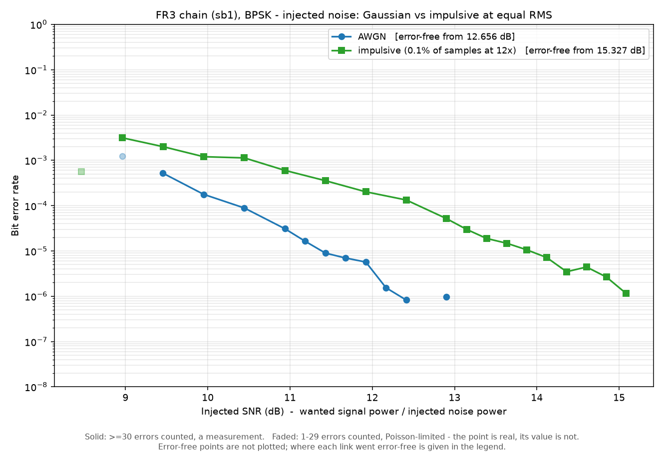
Impulsive noise costs 2.7 dB at the error-free threshold, and the penalty widens as SNR rises —
53× worse at 12.9 dB against 3× worse at 9 dB. That is the signature of a heavy-tailed impairment: as
the Gaussian part becomes negligible the rare spikes dominate what is left, and they are exactly what
the receiver's soft decisions are not built for.
One detail worth noticing, because it looks backwards. Impulsive noise starts decoding earlier — the
first packets appear at 8.0 dB against 8.5 dB for AWGN. At equal RMS, noise concentrated into 0.1 % of
samples is below the Gaussian level for the other 99.9 %, so frame detection has an easier time on
average. The link gets going sooner and then cannot clean up. Averages and tails are different
questions, and a waterfall answers only the second.
¶ Options
| Parameter | Default | What it does |
|---|---|---|
sub |
bpsk |
bpsk, qpsk, 8psk, 16qam, 64qam |
coding |
none |
none, or cc12 for K=7 rate-1/2 convolutional coding — see below |
usrp_freq_hz |
1000000000 |
What both USRPs tune to |
low_lo_hz |
700000000 |
Front-end low-side LO |
high_lo_hz |
10000000000 |
Front-end high-side LO |
amplitude |
0.02 |
Transmit drive. Take it from Step 1. |
tx_gain |
15 |
USRP transmit gain, dB — held fixed while the front end is swept |
rx_gain_db |
50 |
Front-end receive gain — a measured optimum, not a maximum. See Step 3. |
usrp_rx_gain |
30 |
USRP receive gain, dB. Stays under the UBX's 37.5 dB top. |
tx_gains |
10…50 by 2 |
The sweep axis: front-end transmit gain, dB |
stop_below_ber |
0.0001 |
Stops the sweep once it is good enough to be uninteresting |
allow_transmit |
false |
Opt-in for raising a front-end transmit gain |
noise_kind |
awgn |
Step 4 only: awgn, coloured or impulsive |
snr_db |
24:-2:-0.5 |
Step 4 only: sweep range, start:stop:step |
Sweeping the USRP gain and the front-end gain at once tells you nothing about either, so tx_gain is
deliberately held while tx_gains walks.
¶ Forward error correction — coding: cc12
cosmos-run fr3/ofdm-ber.description.yml -e '{"cosmos_parameters": {"coding": "cc12", "noise_kind": "awgn", "snr_db": "3:12:0.5", "allow_transmit": true}}'
The packet stays 96 bytes either way. Coding does not make the packet
longer — it reduces how much of the packet is information: 47 of the 96 bytes
carry data and the rest is the codeword. Nothing else in the chain changes.
That is why the comparison is at equal Es/N0 — same transmit power, same
occupancy, half the throughput. Say so whenever you publish a coded curve
against an uncoded one, because the two are otherwise easy to read as a free
improvement.
The sweep then reports two bit error rates per point:
| Column | Meaning |
|---|---|
ber |
The channel, before the decoder. What the link delivered to it. |
coded_ber |
What was delivered to the application, after decoding. |
coded_bits |
How many bits back that number — decoding is capped per point, so this says what the estimate rests on. |
The gap between them is the coding gain. Measured at 10 GHz against a matched
uncoded control:
| Effective SNR | Channel BER | Delivered BER |
|---|---|---|
| 11.9 dB | 3.5e-4 | 0 (1.5 Mbit) |
| 11.4 dB | 4.3e-4 | 0 (2.3 Mbit) |
| 10.7 dB | 9.6e-4 | 0 (0.75 Mbit) |
| 10.2 dB | 1.9e-3 | 0 (0.26 Mbit) |
| 9.9 dB | 2.9e-3 | 5.7e-6 |
So a channel running at one error in a thousand is delivered clean.
Two honest limits. This is hard-decision decoding — the receiver
slices before the decoder sees it, so soft decisions would be worth roughly
another 2 dB and would mean changing the receiver. And no single "gain in dB"
is quoted here: the uncoded curve never reaches 1e-5 in this SNR range, so
the crossing needed to state one has not been measured.
¶ Running it at FR1 (sub-6 GHz), without the front-ends
The same role, the same flowgraphs and the same five modulations run at FR1 on a plain USRP pair —
set cosmos_fr3_use_upconverters: false and the front-end steps drop out, leaving the USRP's own
transmit gain as the sweep axis. This is how you get 16-QAM and 64-QAM at sub-6 GHz: they have no
graphical path anywhere, so this page is the only route to them regardless of band. Ready-made
descriptions:
# over the air on the grid, 2.4 GHz, B210 pair
cosmos-run sdr/ofdm-ber-qam-grid-txpower.description.yml \
  -e '{"cosmos_parameters": {"sub": "16qam"}}'
Two differences worth knowing. A B210 wants 1 MSps here — it core-dumps its transmitter at 5 MSps
inside gr::tagged_stream_block::general_work — while the X310 in a USRP-2974 is happy at 5. And the
B210's transmit gain steps in 0.25 dB increments over 0–89.75 dB; asking for anything finer
silently rounds and produces duplicate points under different labels.
¶ Why the dense modulations are automated-only
gnuradio.digital.ofdm_tx maps only 1, 2 and 3 bits per symbol and calls exit(1) on anything
else — verified against the installed 3.10.12 and against upstream master. So 16-QAM and 64-QAM are
transmitted by a port of that hierarchical block which takes the payload constellation as a
parameter. The receiver needed no change: it already derives its equalizer, serializer width and header
formatter from a plain payload_mod variable.
The mapping trap. GNU Radio ships more than one 16-QAM generator and they return different
constellation points —qam.qam_constellation(16)is notdigital.constellation_16qam(). A
mismatch is invisible at the receiver and looks exactly like a dead link. Both ends here call the
same generator. If you build your own and BPSK/QPSK decode while 16-QAM does not, this is why.
¶ Verification
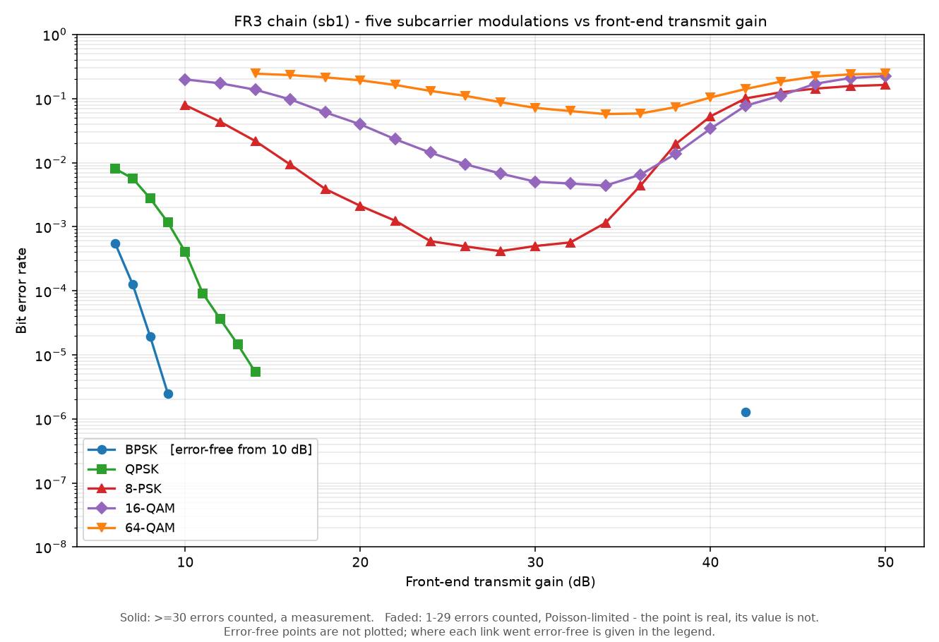
Measured 2026-08-02 on sb1. USRP transmit gain 15 dB, USRP receive gain 30 dB, front-end receive gain
50 dB, sweeping the front-end transmit gain. Each modulation at its own drive level, taken from the
Step 1 probe.
| Modulation | bits/symbol | drive | Best BER | at front-end TX gain | Perfect packets |
|---|---|---|---|---|---|
| BPSK | 1 | 0.02 | 0 | error-free from 10 dB | every packet |
| QPSK | 2 | 0.02 | 5.37e-6 | 14 dB | 133 794 of 133 835 |
| 8-PSK | 3 | 0.02 | 4.15e-4 | 28 dB | 8 565 of 8 723 |
| 16-QAM | 4 | 0.012 | 4.38e-3 | 34 dB | 14 345 of 17 593 |
| 64-QAM | 6 | 0.008 | 5.73e-2 | 34 dB | 358 of 5 344 |
The five curves land in the order theory predicts, each roughly a constellation step to the right of
the last. Nothing decodes below 6 dB on any of them — the OFDM frame detector stops finding
headers, so no payload is emitted and there is no BER to compute. That is an absence, not a floor.
The three dense curves are two-sided: BER falls as transmit gain rises, reaches a minimum, then
climbs again as the chain compresses. 8-PSK's minimum is a broad basin from 24 to 32 dB; 64-QAM's is
narrow and shallow. BPSK is error-free from 10 dB all the way to 40 and shows its first errors only at
42 dB (1.28e-6) — that isolated point on the far right of the figure is the compression side, not a
noise limit, which is why no line joins it to the waterfall.
¶ On the drive level — and why 16-QAM and 64-QAM disagree
The Step 1 probe put the drive optimum well below the 0.02 the PSK family uses — 0.008 for 64-QAM,
0.012 for 16-QAM — with 0.02 apparently past the window for both. Repeating each full transmit-gain
sweep at the probed drive tests that directly:
| at drive 0.02 | at the probed drive | change | |
|---|---|---|---|
| 16-QAM | 6.07e-3 | 4.38e-3 (0.012) | 28 % better |
| 64-QAM | 5.739e-2 | 5.730e-2 (0.008) | 0.2 % — nothing |
So it matters for 16-QAM and not at all for 64-QAM, across drives more than a factor of two apart.
Take the drive from a probe rather than assuming, but do not assume the probe's magnitude either:
it reported 1.7e-1 for 64-QAM at drive 0.02 where two independent transmit-gain sweeps report 5.7e-2
at the same nominal settings.
Two agreeing measurements beat one disagreeing one, so the sweeps are right and the amplitude and
transmit-gain sweep modes are not directly comparable in absolute terms. Use the probe for the
shape of the drive window — where the walls are — not to predict a BER. Why the two modes disagree
is unresolved.
There is a general lesson in that pair of rows worth more than either number. "The drive was wrong, so
these curves are invalid" was a reasonable reading of the probe, and it was half right and half wrong,
in a way no amount of reasoning about the probe could have told you. It cost two re-runs to find out,
which is cheaper than a tutorial built on either version.
¶ Do not read the 64-QAM figure as a distortion limit
5.7e-2 is poor, and it would be easy — and wrong — to write it up as an EVM limit of the chain. That
exact conclusion was reached earlier in this project for 16-QAM and 64-QAM on a different link, on
the strength of a shallow curve slope plus a receive-gain test that made things worse, and it was
wrong: moving the transmitter from 17 m to 7 m, same receiver, took 16-QAM to 9.4e-5 and 64-QAM
from zero perfect packets to 4 584. Both links were simply below the knee of the waterfall.
So the honest statement is: on this chain, at these settings, 64-QAM reaches 5.7e-2 and no further — because
that is exactly what 64-QAM does at this chain's 15.36 dB of effective SNR. The arithmetic is
below; it agrees to within 2 %.
Tried: front-end receive gain at 35, 50 and 60 dB (50 is best), front-end transmit gain across its full
range, and two drive levels a factor of 2.5 apart — which changed the answer by 0.2 %. Not tried: a
narrower sample rate, which buys SNR per subcarrier; re-balancing gain between the USRP and the front
end rather than between the two front ends; and anything that shortens the path. Treat the figure as a
measurement of this link, not a property of 64-QAM.
¶ What actually limits this chain
The three dense modulations all settle at the BER a ≈15 dB effective SNR
implies. That is a ceiling which does not care what is being sent, and it is
worth knowing what it is not, because six plausible explanations have been
tested and eliminated:
| Explanation | How it was ruled out |
|---|---|
| Noise power | BER flat against receive gain over 17.5 dB |
| Phase drift within a symbol | BER flat against symbol duration over 4× (5/10/20 MSps) |
| Transmit overdrive | Two full sweeps at drives 2.5× apart agree to 0.2 % |
| Frequency-selective fading | Channel response flat to 3–4 dB, zero carriers >6 dB down |
| Receive clipping / PAPR | Removing 4 % clipping entirely changed 16-QAM by nothing |
| LO phase noise | Common phase error does not scale with carrier frequency (below) |
Measuring the error vector directly and splitting it by mechanism gives
15.36 dB, confirming by a completely different route the number the BER
curves imply:
| Mechanism | share of error | alone |
|---|---|---|
| random residual (thermal + ICI) | 70 % | 16.9 dB |
| common phase error | 25 % | 21.4 dB (2.9° rms) |
| deterministic per-carrier (spurs) | 4 % | 29.3 dB |
| mirror / IQ imbalance | 0.7 % | 36.7 dB |
So IQ imbalance is not worth calibrating here — the image is 37 dB down and
contributes under one percent of the error. Perfect correction would buy about
0.03 dB. What remains is thermal noise and inter-carrier interference, which no
gain setting and no calibration removes.
¶ And the positive check: the chain is doing exactly what 15.36 dB predicts
Ruling six things out says what the ceiling is not. The confirmation that it is
only SNR is arithmetic: put 15.36 dB into the textbook uncoded-AWGN
expressions and compare with what was measured, each modulation at its own
probed drive.
| Modulation | Uncoded AWGN theory at 15.36 dB | Measured on this chain | ratio |
|---|---|---|---|
| 8-PSK | 5.04 × 10⁻⁴ | 4.15 × 10⁻⁴ | 0.82 |
| 16-QAM | 3.29 × 10⁻³ | 4.38 × 10⁻³ | 1.33 |
| 64-QAM | 5.86 × 10⁻² | 5.73 × 10⁻² | 0.98 |
Three constellations, spanning two and a half decades of BER, all within a
third of theory and 64-QAM within two percent. This chain is not
distortion-limited, EVM-limited, or defective in any way — it is an ordinary
AWGN channel with 15.36 dB of SNR, and it delivers precisely the error rate
that implies.
So the 5.7 × 10⁻² is not a property of the hardware to be engineered away. It
is what 64-QAM does at 15 dB:
| For 64-QAM to reach | it needs |
|---|---|
| 10⁻² | 19.7 dB |
| 10⁻³ | 22.5 dB |
| 10⁻⁴ | 24.3 dB |
| 10⁻⁵ | 25.6 dB |
The chain provides 15.36 dB. Nothing short of more link margin — shorter
path, more front-end gain, narrower sample rate — moves that number, and no
amount of re-tuning drive or receive gain will, which is exactly what the two
drive sweeps 2.5× apart showed when they agreed to 0.2 %.
This is the same trap as everywhere else in these two pages, in its final
form. A BER that will not improve looks like a defect to be found. Twice here
it was simply the operating point: once the drive, once the end of the sweep
axis, and now the link budget itself. Before hunting a mechanism, check what
the SNR you actually have predicts — see the
FR1 laboratory, where the same
64-QAM reaches 8.5 × 10⁻⁶ on a grid X310 pair for no reason other than 52 dB
of margin instead of 15.
¶ Re-verified 2026-09-08 — and two framework bugs this page's own commands hit
Everything above was measured 2026-08-02. Re-running it six weeks later found
two defects in the shipped framework, both of which affected anyone following
these instructions, and neither of which is visible in the output.
1. A descending SNR sweep stopped after its first point. The sweep driver
has two early-stops, and both assume the sweep ASCENDS — "every higher SNR is
also clean" is a reason to stop only when the higher SNRs are still ahead of
you. snr_db defaults to 24:-2:-0.5, which descends from 24 dB, so the first
point is the highest SNR and is clean by construction. The run measured one
point, wrote a one-row CSV, printed "first error-free point — stopping" and
exited 0. A waterfall that is a single dot still reads as a successful run.
Fixed in engine 0.1.0-279; a descending sweep now says up front that its
early-exits are disabled.
2. This experiment ran 15 dB below the receive gain this page recommends.
fr3/ofdm-ber.description.yml hardcoded front-end rx_gain_db: 35 and did not
expose it, while the other three FR3 descriptions and Step 3 above all use
50 dB — a measured optimum, not a maximum. Fixed in 0.1.0-280;
tx_gain_db, rx_gain_db and samp_rate are now parameters.
Take the version note seriously: on anything before 0.1.0-280 the default
BER command produces a single point at a sub-optimal receive gain.
¶ What the re-run measured
Same chain, same 300 MHz IF offset, RF 10.3 GHz, each modulation at its own
probed drive, front-end receive gain 50 dB:
| probe (no injected noise) | sweep, best point | perfect frames | |
|---|---|---|---|
| BPSK | — | error-free to ~13 dB, wall at 8.5 dB | 15 000+/point |
| 16-QAM | 1.08e-02 at drive 0.006 | 2.04e-02 at 24.3 dB | 7 815 |
| 64-QAM | 8.85e-02 at drive 0.006 | 1.07e-01 at 23.5 dB | 0 |
Roughly 2× worse than the 2026-08-02 figures — same order, so read this as
a chain slightly degraded, not as a different explanation. The BPSK waterfall
is clean and textbook: error-free above ~13 dB, four decades of BER across
12.5 → 9 dB, and the frame-detector wall at 8.5 dB where sync fails outright.
¶ The constellation code is not the cause — this was tested, not assumed
It is tempting to blame the ported 16/64/256-QAM transmitter. A mapping or
labelling mismatch produces a BER floor that does not move with SNR, which is
the same fingerprint as an EVM ceiling, so no RF measurement can separate
them. Software loopback can, because it puts no radio in the path:
mod       bps   prediff   BER(no noise)
bpsk      1     False     0.000e+00   CLEAN
qpsk      2     False     0.000e+00   CLEAN
8psk      3     False     0.000e+00   CLEAN
16qam     4     False     0.000e+00   CLEAN
64qam     6     False     0.000e+00   CLEAN
256qam    8     False     0.000e+00   CLEAN
Map → demap round-trips losslessly at every order, and apply_pre_diff_code is
False throughout, so the differential-coding trap is not in play either. The
transmitter port is exonerated. Note the limit of that claim: it tests the
constellation, not the OFDM equalizer, pilots, channel estimation or timing.
¶ And gain is not the lever
Raising front-end receive gain 35 → 50 dB bought 7.0 dB of margin (25.7 →
32.7 dB above floor) and moved 64-QAM BER by 3 % — 1.10e-01 to 1.07e-01,
zero perfect frames either way.
That does not overturn the 15.36 dB analysis above, and it would be easy to
misread it as doing so. The "margin" figure is received RMS over a noise floor
measured with the transmitter OFF, so it sees thermal noise only and is blind
to any signal-proportional impairment; it is not the same quantity as the
effective SNR derived from the error vector. What the gain test does establish
is narrower and still useful: receive gain is not the lever here, so a
reader whose dense-constellation BER will not improve should stop turning that
knob. The error-vector decomposition above remains the better evidence for
what the ceiling is.
¶ The chain works across the whole 6–24 GHz band
Pi-Radio's front-ends cover 6–24 GHz, and both extremes were driven. Change
high_lo_hz and the rest follows — RF = high_lo + (usrp_freq − low_lo), so
6.2 GHz gives 6.5 GHz on air and 21.7 GHz gives 22 GHz.
Measured at matched received power, all three with no clipping:
| RF | effective SNR | common phase error | image rejection | channel flatness |
|---|---|---|---|---|
| 6.5 GHz | 10.8 dB | 5.05° | 33.9 dB | 6.9 dB p-p |
| 10.3 GHz | 14.8 dB | 3.92° | 38.5 dB | 3.2 dB p-p |
| 22 GHz | 9.5 dB | 5.61° | 35.4 dB | 4.8 dB p-p |
The link closes at both ends of the band and the channel stays flat throughout —
no subcarrier is ever more than 6 dB down.
And this is what retires the phase-noise explanation. Oscillator phase noise
scales with carrier frequency, so going from 6.5 to 22 GHz — a factor of 3.4 —
should take the common phase error from 5.05° to about 17°. It measured
5.61°, and the middle frequency has the lowest value, which no
phase-noise mechanism produces. The common phase error instead sits at a roughly
constant 3× the phase estimator's own noise floor at all three frequencies: it
is tracking the noise, not the carrier.
Matched received power is not matched SNR. At the same gains the three
frequencies differ by 24 dB in received power — 10.3 GHz is much the
strongest, being the design point — so 22 GHz needed the receive chain near
maximum and more of its power is amplified front-end noise. The effective-SNR
column therefore mixes antenna and path efficiency with noise figure and does
not separate them. The phase-error column does not depend on that, being a
phase measurement rather than a power one.
Read the packet count next to the BER. Frame detection fails well before the payload becomes
unreadable, so a BER computed over a handful of surviving frames describes a link that has already
stopped being usable. On this chain 64-QAM at 50 dB still reports 2.4e-1 — from 158 packets, against
5 248 at the optimum.
Each run also writes a SigMF metadata record carrying the frequency plan, gains, drive level and every
sweep point — enough to reproduce the curve.
¶ Cleanup
The playbook restores the front-ends and stops the transmitter itself, including on failure. When you
are finished with the nodes:
omf tell -a offh -t sdr1-piradio,sdr2-piradio
¶ Troubleshooting
| Symptom | Likely cause | Fix |
|---|---|---|
| BER stuck at a few percent and no receive-side change moves it | transmitter overdrive | Lower amplitude. Run the Step 1 drive probe. |
| A "floor" that shifts when you change any gain | it was never a floor | Keep going — see Step 3 |
| Curve flattens at the good end of a noise sweep | injected noise has hit the link's margin over thermal | Use transmit power, or raise transmit gain |
| No decode at all, plenty of signal | IF sitting on the front-end's LO leakage | Keep ≥100 MHz between usrp_freq_hz and low_lo_hz |
| Numbers look plausible but the link is dead | UHD picked a networked N310 | --dev-args resource=RIO0, always |
| Flat curve at the top of a gain sweep | UHD silently clamped at the UBX's 31.5/37.5 dB | Sweep the front end, not the radio |
| Gain set, nothing changed | firmware returns HTTP 200 on rejection | Read the value back |
SSH refuses your key, password root works |
node is still in the PXE stage image | omf tell offh then on |
uhd_find_devices reports nothing |
queried without resource=RIO0 |
Pass it; the X310 then reports as product X310 |
No SDR matching resource=RIO0 is visible |
another run is holding the radio | Wait for it; this is contention, not a dead device |
¶ The constellation display can lie to you
ofdm_equalizer_simpledfesnaps its output onto the constellation unless its ninth argument,
enable_soft_output, is true. A constellation fed from the default equalizer shows two flawless
points at ±1 on a link measuring 2.4e-2 BER. The graphical flowgraphs in the companion tutorial
enable soft output; if you build your own and the constellation looks impossibly clean, that is why.
It changes no decision and BER is unaffected.
¶ References
- Graphical OFDM BER, BPSK/QPSK/8-PSK: OFDM BER experiments
- Other FR3 tutorials: Sine wave · Analog FM · Amarisoft 5G NR
- Hardware: FR3 · SDRs
- Shared setup: Make a reservation · SSH / console
- Pi-Radio's own GNU Radio OFDM example: https://www.pi-rad.io/home/demos-tutorials/fr3-2-ch-sdr/gnu-radio-ofdm-example-at-fr3
- The
ofdm_txbits-per-symbol limit: https://github.com/gnuradio/gnuradio/issues/7487 - SigMF: https://github.com/sigmf/SigMF
Author(s): COSMOS team · Last verified: 2026-09-08 (BPSK waterfall, 16-QAM and 64-QAM re-measured on sb1 at front-end receive gain 50 dB with drives taken from fresh probes; constellation loopback clean at all six modulations; two framework bugs found and fixed — see the re-verification section). Previously 2026-08-02 (all five subcarrier modulations swept against front-end transmit gain, each at its own probed drive; receive-gain optimum located at 50 dB; AWGN and impulsive noise injection on the same link) · Tested image/release: baseline-sdr.ndz / GNU Radio 3.10.12 / UHD 4.9.0 · Tags: fr3, ofdm, ber, qam, piradio, usrp-2974, sigmf