¶ mmWave & PAAM
Millimetre-wave experimentation on COSMOS: IBM 28 GHz phased array antenna
modules (PAAMs) and Sivers 60 GHz front-ends. This page brings the whole
subject together - what the hardware is, how you drive it, where the boards
are, and every experiment built on them.
¶ The hardware
| What it is | |
|---|---|
| IBM 28 GHz PAAM | 64 dual-polarized antenna elements in an 8 x 8 array, built from four 32-element phased-array ICs, with concurrent beams in two polarizations. The testbed's flagship beamforming platform. |
| Sivers 60 GHz front-ends | EVK06002 mmWave front-ends, paired with USRPs or RFSoCs for 60 GHz links. |
| RF front-end chains | What sits between the SDR and the array. |
¶ How a phased array actually forms a beam
Before the services below will mean anything, it is worth knowing what theta,
phi and elements do to the signal. You can work all of it out without a
reservation and without touching a board - the geometry is known, so the beam
is computable:
curl -O https://www.cosmos-lab.org/files/tutorials/mmwave-paam/paam_beam.py
python3 paam_beam.py --elements all --theta 0 --phi 0
It takes the same arguments the array_mgmt service takes, so you can
predict the pattern, then configure the array and see whether the hardware
agrees. Only Python 3 is needed.
            +- element 1 --[ phase ]--[ PA / LNA ]-+
  3 GHz IF -+- element 2 --[ phase ]--[ PA / LNA ]-+--> one beam at (theta, phi)
            |       ...                            |
            +- element 64 -[ phase ]--[ PA / LNA ]-+
                               ^
                   array_mgmt sets these 64 numbers,
                   and theta/phi is all you have to say
¶ 1. Steering is a delay, and a delay is a phase
A wavefront leaving at an angle reaches the near edge of the array before the
far edge. Delay each element by exactly the difference and every contribution
arrives in step in that one direction - and out of step everywhere else. At a
single frequency a delay is just a phase, and a phase shifter per element is
precisely what the PAAM provides.
The required step between neighbours is dphi = -k d sin(theta). At 28 GHz
with half-wavelength spacing that works out to a round number:
python3 paam_beam.py --elements 1-8 --theta 30 --phases
1. geometry   8 of 64 elements, 28.0 GHz, lambda = 10.71 mm
              spacing 5.35 mm = 0.500 lambda  (assumed)
2. steering   beam commanded to theta=+30.0 phi=+0.0
              per-element phase shifts span 630.0 degrees
              element  phase (deg)
                    1     -45.0
                    2    -135.0
                    3    +135.0
                    4     +45.0
                    5     -45.0
                    6    -135.0
                    7    +135.0
                    8     +45.0
Ninety degrees per element, every element, all the way across. Point it at
broadside instead and every phase is zero - theta=0 needs no phase shifter at
all, which is the cheapest sanity check there is that your steering code works.
¶ 2. Why those phases wrap - and what it costs
Read the list again: it does not run -45, -135, -225, -315. It wraps, because
a phase is only ever known modulo 360 degrees. That has a physical consequence.
If a neighbouring element sits a whole wavelength further along the wavefront,
it arrives in step just as surely as if it sat at zero - so there is a second
direction in which the whole array adds up, at full strength. It is called a
grating lobe, and it is a beam you did not ask for:
python3 paam_beam.py --elements all --theta 30 --spacing 10.7069
5. grating    spacing is 1.00 lambda > 0.5, so the beam is NOT unique:
              a second full-strength beam appears at theta=-30 deg.
              Half-wavelength pitch is what rules this out.
sin(theta_g) = sin(theta_0) +/- lambda/d only lands inside the visible region
when d > lambda/2. That single inequality is why essentially every scanning
array ever built, this one included, puts its elements a half wavelength apart.
Try --spacing values on either side of 5.35 mm and watch the second beam walk
in from the horizon.
¶ 3. elements= chooses the beam's shape, not just its strength
This is the part that surprises people. Compare the full array with a single row
and a single column, in two orthogonal cuts:
--elements |
cut along phi=0 |
cut along phi=90 |
|---|---|---|
all (8 x 8) |
12.8 deg | 12.8 deg |
1-8 (one row) |
12.8 deg | no beam at all |
1,9,17,25,33,41,49,57 (one column) |
no beam at all | 12.8 deg |
A row of 8 is just as sharp as the full 64 in the plane the row lies in - the
other 56 elements buy you nothing there. What they buy is the other plane.
Eight elements give you a fan beam, narrow one way and wide the other; 64 give
you a pencil beam. Choosing elements is choosing between them.
Strength is the separate question, and it follows the count:
- receive:
+10 log10(N)of array gain - 64 elements give +18.1 dB - transmit:
+20 log10(N)of EIRP - +36.1 dB - because each element
carries its own power amplifier, so you add power and directivity at once
Sidelobes come along for the ride: a uniformly excited array puts its first
sidelobe about 13 dB below the main beam, which is what the pattern cut
shows and is not something you can steer away.
¶ 4. What this means for the SB2 boards
The partial connection noted below is not a footnote, it is a different antenna.
The elements the SB2 TX port reaches - 1-4, 9-12, 17-20, 25-28 - are a 4 x 4
quadrant, so:
python3 paam_beam.py --elements 1-4,9-12,17-20,25-28 --theta 0
3. gain       16 elements in step give 16.0x the field of one
              = +12.0 dB of array gain on receive (10log10 N)
              = +24.1 dB of EIRP on transmit, since each element
                brings its own power amplifier (20log10 N)
4. beamwidth  26.3 deg at -3 dB, peak at theta=+0.0
26 degrees and +12 dB on SB2, against 13 degrees and +18.1 dB on SB1. Same
board, same service call - a different antenna, because a different set of
elements is wired to the radio.
¶ 5. Does any of this match the real board? Yes - it was measured
None of the above is a model someone hoped would apply. The same arrays, driven
through the same API, were measured on sb1 and published [4]:
| measured on sb1 | computed on this page | |
|---|---|---|
| half-power beamwidth, 16 elements | 26 deg | 26.3 deg |
| peak power, 8 elements against 16 | ~6 dB lower | 20 log10(16/8) = 6.0 dB |
| 8 elements, two orthogonal planes | "a large difference ... due to the asymmetric number of elements on the x and y axes" | a fan beam - sharp in one plane, no beam in the other |
Three things follow, and each one closes a loop opened earlier on this page:
- 26 degrees is the best evidence we have that the pitch really is a half
wavelength. 26.3 deg is whatlambda/2predicts for a 4 x 4 sub-array, so
the measurement lands within 0.3 deg of it; a materially different spacing
would not. Turned around, a 26 deg width back-solves to a pitch of
0.49 lambda, about 5.2 mm at 28 GHz. Treat that as corroboration, not as
metrology - it was measured indoors, in multipath, without rotating the board. - The 6 dB confirms that transmit follows
20 log10(N), not10 log10(N).
Doubling the elements doubles the radiated power and halves the beamwidth,
and you collect both at once because every element has its own amplifier. Had
the measurement come back 3 dB, only one of the two would have been happening. - The third row is point 3, measured. What sets the beamwidth in a plane is
the number of elements along that axis, not the total switched on.
The authors' own caveat applies: the board was not mechanically rotated during
those sweeps, so these are electronically steered cuts, not standard antenna
pattern measurements. A peak-to-null ratio of >30 dB was measured alongside them.
Worth doing yourself. The
Basics tutorial sends a
single tone. Send it twice at the same theta, once with elements=28 and once
with elements=all, and the received power should rise by roughly the 36 dB
of point 3. Measuring that is a far better check that the array is working than
reading supply currents.
Expect to fall a little short of the ideal, and understand why - each gap is a
lesson:
- the script computes the array factor only. The real pattern is the array
factor multiplied by the pattern of a single element, which rolls off away
from broadside. This is a large part of whythetais limited to +/-60 deg. - the element pitch is nowhere stated as a number. Half a wavelength is the
standard design point, is what the script assumes, and is corroborated by the
26 deg measurement above - but it is inferred, not quoted. Every beamwidth on
this page scales with it. - mutual coupling between neighbouring elements, and the finite accuracy of
real phase shifters, both take a bite out of the ideal sum. - at short range you may be inside the array's near field, where the idea of a
far-field pattern does not apply at all.
[4] T. Chen, P. Maddala, P. Skrimponis, J. Kolodziejski, A. Adhikari,
H. Hu, Z. Gao, A. Paidimarri, A. Valdes-Garcia, M. Lee, S. Rangan, G. Zussman
and I. Seskar, "Open-access millimeter-wave software-defined radios in the
PAWR COSMOS testbed: design, deployment, and experimentation," Computer
Networks, vol. 234, p. 109922, Oct. 2023.
PDF - the measurements above are in its Section 5.
See also X. Gu et al., "Development of a compact 28-GHz software-defined
phased array for a city-scale wireless research testbed," Proc. IEEE IMS'21,
June 2021 (PDF) for the array itself.
Confirm the angle convention against the hardware before trusting a steered
result. The script uses the standard spherical convention -thetameasured
from broadside,phithe rotation in the plane of the array - which matches
the service'sthetalimit of +/-60 deg, but the service's own convention is
not written down.
¶ Driving it - the services
The arrays and the movable platforms are controlled over HTTP from the sandbox
console, through the AM proxy. Read these before the tutorials: nothing
radiates until the array has been configured.
| Service | What it controls | Needed by |
|---|---|---|
array_mgmt |
Which of the 64 elements are on, transmit or receive, polarization, LO source and beam direction (theta, phi). Every response carries the board's supply currents, so you can confirm the array really switched on. |
every IBM PAAM experiment |
xy_table |
Moves the mobile PAAM platforms on SB1. | the mobility experiments |
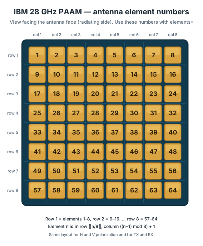
Elements are numbered 1-64, row by row, from the top-left corner as seen
facing the antenna face - and which ones you pick decides the beam's shape,
not merely its strength (see above):
¶ Where the boards are
Boards you can drive with array_mgmt:
| Sandbox | Boards | Note |
|---|---|---|
| SB1 | rfdev4-in1, rfdev4-in2 |
all four quadrants combined - every one of the 64 elements reaches the radio |
| SB1 (mobile) | rfdev-mob4-1, -2, -3 |
combined, and moved with xy_table |
| SB2 | rfdev2-1, rfdev2-2 |
partially connected - the radio's TX port reaches elements 1-4, 9-12, 17-20, 25-28, and its RX port 5-8, 13-16, 21-24, 29-32 |
The 28 GHz arrays integrated into the medium-node housings on the West Harlem
rooftops belong to the BED deployment
(see also outdoor antennas); they are
not driven through the sandbox array_mgmt boards above. Sandbox layouts:
SB1 and
SB2.
¶ Tutorials
| Tutorial | About |
|---|---|
| 802.11ad Preamble Processing with RFNoC and Sivers 60 GHz Front-Ends on COSMOS SB1 | This tutorial demonstrates how to use RFNoC 802.11ad preamble processing blocks with Sivers 60 GHz mmWave front-ends on COSMOS SB1, trans… |
| IBM 28 GHz PAAM Basics | Transmit and receive a single tone at 28 GHz using IBM Phased Array Antenna Modules (PAAMs) and USRP N310 SDRs in the COSMOS sandbox (SB1… |
| IBM 28 GHz PAAM MIMO with Agora-UHD Real-Time Baseband Processing | Integrate IBM 28 GHz Phased Array Antenna Module (PAAM) boards with USRP N310 SDRs on COSMOS SB2 and run a real-time MIMO baseband proces… |
| IBM 28 GHz PAAM: Link Rate vs. SNR with MAMBAS | Demonstrate multi-user analog beamforming at 28 GHz on the COSMOS SB2 testbed |
| Millimeter Wave Experimentation with Xilinx RFSoC and Sivers PAAM on COSMOS SB1 | Set up two RFSoC-backed mmWave nodes on COSMOS SB1, configure the RF switches and Sivers PAAM arrays, and run basic single-node, two-node… |
| mmWave PAAM Mobile Beam-Steering Experiment | Transmit and receive mmWave signals between two mobile PAAM (Phased-Array Antenna Module) nodes on sb1.cosmos-lab.org, then run beam-stee… |
| Mobile PAAM OFDM Link | Run an OFDM link at 28 GHz between two mobile phased-array antenna modules (PAAMs), each paired with a USRP-2974 SDR, using GNU Radio Com… |
| OFDM Over 28 GHz Phased Arrays (FR2): BER, Beam Angle, and the Receiver It Takes | Measure OFDM bit-error rate over the SB1 PAAM pair against SNR and beam angle, and take apart in numpy the receiver it needs: two free-running 28 GHz PLLs make the stock GNU Radio receiver floor at 3.5e-3, and per-symbol pilot tracking (the idea behind 5G PT-RS) and three more receiver changes take QPSK to 8e-5. |
| Savannah: Efficient mmWave Baseband Processing with Minimal and Heterogeneous Resources | Demonstrate Savannah, a framework for efficient real-time mmWave baseband processing on COSMOS SB2, using IBM 28 GHz PAAMs and USRP N310 … |
| Transmit and Receive at 60 GHz Using Sivers mmWave Front-Ends on sb1 | Transmit and receive a sine wave through the 60 GHz Sivers EVK06002 mmWave |
| GNU Radio CFO Estimation with OFDM and IBM 28 GHz mmWave (USRP N310) | Carrier frequency offset estimation over a 28 GHz PAAM link with USRP N310 radios. Filed under SDR & GNU Radio; listed here because it runs on the PAAMs. |
Part of the COSMOS Tutorials collection.